4.4 RETIMING TECHNIQUES
This section considers some techniques used for retiming. First, two special cases of retiming, namely, cutset retiming and pipelining, are considered. Two algorithms are then considered for retiming to minimize the clock period and retiming to minimize the number of registers that are required to implement the circuit.
4.4.1 Cutset Retiming and Pipelining
Cutset retiming is a useful technique that is a special case of retiming. A cutset is a set of edges that can be removed from the graph to create 2 disconnected subgraphs. Cutset retiming only affects the weights of the edges in the cutset. If the 2 disconnected subgraphs are labeled G1 and G2, then cutset retiming consists of adding k delays to each edge from G1 to G2 and removing k delays from each edge from G2 to G1. For example, a cutset is shown with a dashed line in Fig. 4.4(a). The 3 edges in the cutset are 2 → 1, 3 → 2, and 1 → 4. The 2 subgraphs G1 and G2 found by removing the 3 edges in the cutset are shown in Fig. 4.4(b). For k = 1, the result of cutset retiming is shown in Fig. 4.4(c). The edges from G1 to G2 are 3 → 2 and 1→ 4, and one delay is added to each of these edges. The edge from G2 to G1 is 2 → 1, and one delay is subtracted from this edge.
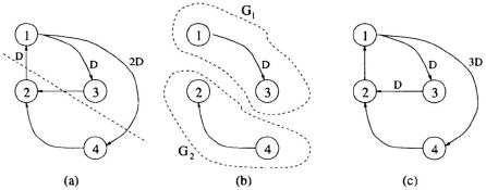
Fig. 4.4 (a) The unretimed DFG with a cutset shown as a dashed line. (b) The 2 graphs G1 and G2 formed by removing the edges in the cutset. ...
Get VLSI Digital Signal Processing Systems: Design and Implementation now with the O’Reilly learning platform.
O’Reilly members experience books, live events, courses curated by job role, and more from O’Reilly and nearly 200 top publishers.

