An interactive live jellyfish forest, with hundreds of jellies pulsating and rays of sunlight streaming from the surface of the sea to the murky depths below—under your control. A networked virtual reality simulation of the human body, including the skeletal, circulatory, and other major systems: with your mouse you can peel back the layers of the body, drop pins on interesting parts for future reference, and share a hyperlink with colleagues and students. An immersive massively multiplayer universe, filled with your Twitter friends and followers. No, you haven’t accidentally channel-flipped to an episode of PBS's Nova, and you’re not watching a trailer for the latest Ridley Scott film. This stuff of the future is running in your web browser—right now. It’s called WebGL.
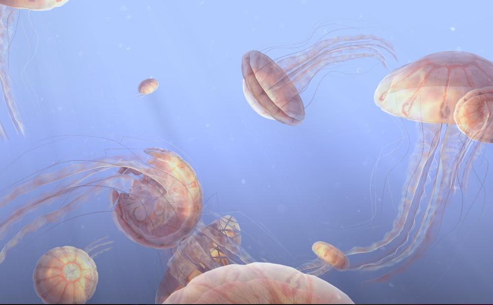
Figure 1-1. WebGL jellyfish simulation (http://chrysaora.com/), reproduced with permission from Aleksander Rodic
WebGL is the new standard for 3D graphics on the Web. With WebGL, developers can harness the full power of the computer’s graphics rendering hardware using only JavaScript, a web browser, and a standard web technology stack. Before WebGL, developers had to rely on plug-ins or native applications and ask their users to download and install custom software in order to deliver a true 3D experience.
WebGL is part of the HTML5 family of technologies. While not in the official specification, it is shipped with most browsers that support HTML5. Like Web Workers, Web Sockets, and other technologies outside the official W3C recommendations, WebGL is an essential component in an emerging suite that is transforming the modern browser into a first-class application platform.
WebGL works on the majority of desktops, as well as a growing number of mobile browsers. There are millions of WebGL-enabled seats already installed, most likely including the machines you run at home and in your office. WebGL is at the center of a vibrant and growing ecosystem that is making the web experience more visually rich and engaging. There are hundreds of sites, applications, and tools being developed, with applications ranging from games to data visualization, computer-aided design, and consumer retail.
While the low-level nature of the WebGL API may appear daunting at first, there are several open source JavaScript toolkits that take the grunt work out of development. I want to be careful not to oversell this—3D is still hard work—but these tools at least make it possible for mere mortals with modest web development experience to get into the WebGL business. So maybe it’s finally time for you to create that hit game you always wanted to make. Or maybe today is the day when you blow your boss’s mind with a dazzling intro graphic for your home page.
In this chapter, we will take a quick tour of the low-level underpinnings of WebGL to give you a foundation. For the majority of the book, we will use a high-level 3D toolkit, Three.js, which hides many of the messy details. But it is important to know what these tools are built upon, so let’s start by exploring WebGL’s core concepts and API.
WebGL is developed and maintained by the Khronos Group, the standards body that also governs OpenGL, COLLADA, and other specifications you may have heard of. Here is the official description of WebGL, from the Khronos website:
WebGL is a royalty-free, cross-platform API that brings OpenGL ES 2.0 to the web as a 3D drawing context within HTML, exposed as low-level Document Object Model interfaces. It uses the OpenGL shading language, GLSL ES, and can be cleanly combined with other web content that is layered on top or underneath the 3D content. It is ideally suited for dynamic 3D web applications in the JavaScript programming language, and will be fully integrated in leading web browsers.
This definition comprises several core ideas. Let’s deconstruct them here:
- WebGL is an API
WebGL is accessed exclusively through a set of JavaScript programming interfaces; there are no accompanying tags like there are with HTML. 3D rendering in WebGL is analogous to 2D drawing using the
Canvaselement, in that it is all done through JavaScript API calls. In fact, access to WebGL is provided using the existingCanvaselement and obtaining a special drawing context specific to WebGL.- WebGL is based on OpenGL ES 2.0
OpenGL ES is an adaption of the long-established 3D rendering standard OpenGL. The “ES” stands for “embedded systems,” meaning that it has been tailored for use in small computing devices, most notably phones and tablets. OpenGL ES is the API that powers 3D graphics for the iPhone, the iPad, and Android phones and tablets. . WebGL’s designers felt that, by basing the API on OpenGL ES’s small footprint, delivering a consistent, cross-platform, cross-browser 3D API for the Web would be more achievable.
- WebGL combines with other web content
WebGL layers on top of or underneath other page content. The 3D canvas can take up just a portion of the page, or the whole page. It can reside inside
<div>tags that are z-ordered. This means that you develop your 3D graphics using WebGL, but all your other elements are built using familiar old HTML. The browser composites (combines) all of the graphics on the page into a seamless experience for the user.- WebGL is built for dynamic web applications
WebGL has been designed with web delivery in mind. WebGL starts with OpenGL ES, but it has been adapted with specific features that integrate well with web browsers, work with the JavaScript language, and are friendly for web delivery.
- WebGL is cross-platform
WebGL is capable of running on any operating system, on devices ranging from phones and tablets to desktop computers.
- WebGL is royalty-free
Like all open web specifications, WebGL is free to use. Nobody will be asking you to pay royalties for the privilege.
The makers of Chrome, Firefox, Safari, and Opera have committed significant resources to developing and supporting WebGL, and engineers from these teams are also key members of the working group that develops the specification. The WebGL specification process is open to all Khronos members, and there are also mailing lists open to the public. See Appendix A for mailing list information and other specification resources.
As sexist as the infamous quote may be, I have to say that whenever I code something in 3D, I, like Barbie, get a very strong urge to indulge in shop therapy. It’s hard stuff and it often involves more than a little math. Luckily, you won’t have to be a math whiz to build something in WebGL; we are going to use libraries that do most of the hard work for us. But it is important to understand what’s going on under the hood, and to that end, here is my attempt to summarize the entire discipline of interactive 3D graphics in a few pages.
3D drawing takes place, not surprisingly, in a 3D coordinate system. Anyone familiar with 2D Cartesian coordinate
systems such as you find on graph paper, or in the window coordinates of an HTML
document, knows about x and y values.
These 2D coordinates define where <div>
tags are located on a page, or where the virtual “pen” or “brush” draws in the case
of the HTML Canvas element. Similarly, 3D
drawing takes place in a 3D coordinate system, where there is an additional
coordinate, z, which describes depth (i.e., how far into or out
of the screen an object is drawn). The WebGL coordinate system is arranged as
depicted in Figure 1-2, with
x running horizontally left to right,
y running vertically bottom to top, and positive
z coming out of the screen.
If you are already comfortable with the concept of the 2D coordinate system, I think the transition to a 3D coordinate system is pretty straightforward. However, from here on, things get a little complicated.
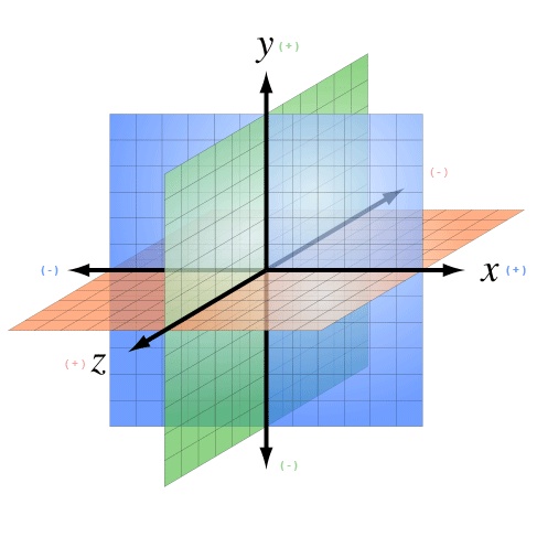
Figure 1-2. A 3D coordinate system (https://commons.wikimedia.org/wiki/File:3D_coordinate_system.svg; Creative Commons Attribution-Share Alike 3.0 Unported license)
While there are several ways to draw 3D graphics, by far the most common is to use a mesh. A mesh is an object composed of one or more polygonal shapes, constructed out of vertices (x, y, z triples) defining coordinate positions in 3D space. The polygons most typically used in meshes are triangles (groups of three vertices) and quads (groups of four vertices). 3D meshes are often referred to as models.
Figure 1-3 illustrates a 3D mesh. The dark lines outline the quads that comprise the mesh, defining the shape of the face. (You would not see these lines in the final rendered image; they are included for reference.) The x, y, and z components of the mesh’s vertices define the shape only; surface properties of the mesh, such as the color and shading, are defined using additional attributes, as we will discuss shortly.
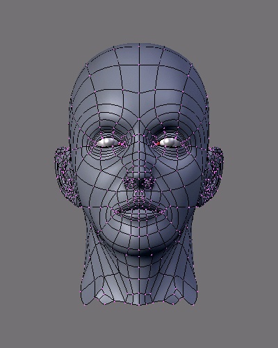
Figure 1-3. A 3D mesh (http://upload.wikimedia.org/wikipedia/commons/8/88/Blender3D_UVTexTut1.png; Creative Commons Attribution-Share Alike 3.0 Unported license)
The surface of a mesh is defined using additional attributes beyond the x, y, and z vertex positions. Surface attributes can be as simple as a single solid color, or they can be complex, comprising several pieces of information that define, for example, how light reflects off the object or how shiny the object looks. Surface information can also be represented using one or more bitmaps, known as texture maps (or simply textures). Textures can define the literal surface look (such as an image printed on a t-shirt), or they can be combined with other textures to achieve sophisticated effects such as bumpiness or iridescence. In most graphics systems, the surface properties of a mesh are referred to collectively as materials. Materials typically rely on the presence of one or more lights, which (as you may have guessed) define how a scene is illuminated.
The head in Figure 1-3 has a material with a purple color and shading defined by a light source emanating from the left of the model (note the shadows on the right side of the face).
3D meshes are defined by the positions of their vertices. It would get awfully tedious to change a mesh’s vertex positions every time you want to move it to a different part of the view, especially if the mesh were continually moving across the screen or otherwise animating. For this reason, most 3D systems support transforms, operations that move the mesh by a relative amount without having to loop through every vertex, explicitly changing its position. Transforms allow a rendered mesh to be scaled, rotated, and translated (moved) around, without actually changing any values in its vertices.
A transform is typically represented by a matrix, a mathematical object containing an array of values used to compute the transformed positions of vertices. If you are a linear algebra geek like me, you probably feel comfortable with this idea. If not, please don’t break into a cold sweat. The Three.js toolkit we are using in this book lets us treat matrices like black boxes: we just say translate, rotate, or scale and the right thing happens.
Every rendered scene requires a point of view from which the user will be viewing it. 3D systems typically use a camera, an object that defines where (relative to the scene) the user is positioned and oriented, as well as other real-world camera properties such as the size of the field of view, which defines perspective (i.e., objects farther away appearing smaller). The camera’s properties combine to deliver the final rendered image of a 3D scene into a 2D viewport defined by the window or canvas.
Cameras are almost always represented using a couple of matrices. The first matrix defines the position and orientation of the camera, much like the matrix used for transforms (see the earlier discussion). The second matrix is a specialized one that represents the translation from the 3D coordinates of the camera into the 2D drawing space of the viewport. It is called the projection matrix. I know—sigh—there’s that pesky math again! But the details of camera matrices are nicely hidden in most toolkits, so you usually can just point, shoot, and render.
Figure 1-4 depicts the core concepts of the camera, viewport, and projection. At the lower left, we see an icon of an eye; this represents the location of the camera. The red vector pointing to the right (in this diagram labeled as the x-axis) represents the direction in which the camera is pointing. The blue cubes are the objects in the 3D scene. The green and red rectangles are, respectively, the near and far clipping planes. These two planes define the boundaries of a subset of the 3D space, known as the view volume or view frustum. Only objects within the view volume are actually rendered to the screen. The near clipping plane is equivalent to the viewport, where we will see the final rendered image.
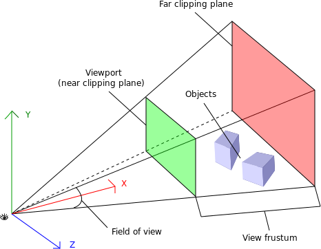
Figure 1-4. Camera, viewport, and projection (http://obviam.net/index.php/3d-programming-with-android-projections-perspective/), reproduced with permission
Cameras are extremely powerful, as they ultimately define the viewer’s relationship to a 3D scene and provide a sense of realism. They also provide another weapon in the animator’s arsenal: by dynamically moving the camera around, you can create cinematic effects and control the narrative experience.
There is one last topic before we conclude our exploration of 3D graphics: shaders. In order to render the final image for a mesh, a developer must define exactly how vertices, transforms, materials, lights, and the camera interact with one another to create that image. This is done using shaders. A shader (also known as a programmable shader) is a chunk of program code that implements algorithms to get the pixels for a mesh onto the screen. Shaders are typically defined in a high-level C-like language and compiled into code usable by the graphics processing unit (GPU). Most modern computers come equipped with a GPU, a processor separate from the CPU that is dedicated to rendering 3D graphics.
If you read my earlier decoded definition of WebGL carefully, you may have noticed that I glossed over one bit. From the official Khronos description:
Unlike many graphics systems, where shaders are an optional and/or advanced feature, WebGL requires shaders. You heard me right: when you program in WebGL, you must define shaders or your graphics won’t show up on the screen. WebGL implementations assume the presence of a GPU. The GPU understands vertices, textures, and little else; it has no concept of material, light, or transform. The translation between those high-level inputs and what the GPU puts on the screen is done by the shader, and the shader is created by the developer.
So now you know why I didn’t bring up this topic earlier: I didn’t want to scare you! Shader programming can be pretty intimidating, and writing a C-like program, short though it may be, seems like an awfully high price to pay just to get an image on the screen. However, take heart: many popular libraries written for WebGL come with prebuilt shaders that you can just drop into your code and are powerful enough to cover all your conceivable shading needs.
Note
I should note here that shaders aren’t only about pain and suffering. They exist for a very good reason. Shaders give the graphics programmer full control over every vertex and pixel that gets rendered. This power can be used to create the most awesome effects, from uncanny photorealism (such as the jellyfish in Figure 1-1) to cartoonish fantasy. But with this great power also comes great responsibility. Shaders are an advanced topic, and I don’t want to climb that mountain together unless we have a thorough understanding of the basics. That’s why the examples in this book will stick to using simple shaders.
The basic concepts of interactive graphics haven’t changed much over the past several years. Implementations, however, are continually evolving, especially due to the recent proliferation of devices and operating systems. Bedrock among these changing tides has been OpenGL. Originally developed in the late 1980s, OpenGL has been an industry-standard API for a very long time, having endured competitive threats from Microsoft DirectX to emerge as the undisputed standard for programming 3D graphics.
But not all OpenGLs are the same. The characteristics of various platforms, including desktop computers, set-top televisions, smartphones, and tablets, are so divergent that different editions of OpenGL had to be developed. OpenGL ES (for “embedded systems”) is the version of OpenGL developed to run on small devices such as set-top TVs and smartphones. Perhaps unforeseen at the time of its development, it turns out that OpenGL ES forms the ideal core for WebGL. It is small and lean, which means that not only is it (relatively) straightforward to implement in a browser, but it makes it much more likely that the developers of the different browsers implement it consistently, and that a WebGL application written for one browser will work identically in another browser.
All of this high-performance, portable goodness comes with a downside. The lean nature of WebGL puts the onus on application developers to layer on top of it their own object models, scene graphs, display lists, and other structures that many veteran graphics programmers have come to take for granted. Of more concern is that, to the average web developer, WebGL represents a steep learning curve full of truly alien concepts. The good news here is that there are several open source code libraries out there that make WebGL development quite approachable, and even fun. Think of them as existing at the level of jQuery or Prototype.js, though the analogy is rough at best. We will be talking about one such library, Three.js, in just a few short pages. But before we get to that, we are going to take a quick tour of the underpinnings, the drive train if you will, of WebGL.
At the end of the day, WebGL is just a drawing library—a drawing library on steroids, granted, considering that the graphics you can draw with WebGL are truly awe-inspiring and take full advantage of the powerful GPU hardware on most machines today. But it is really just another kind of canvas, akin to the 2D Canvas supported in all HTML5 browsers. In fact, WebGL actually uses the HTML5 <canvas> element to get 3D graphics into the browser page.
In order to render WebGL into a page, an application must, at a minimum, perform the following steps:
Create a canvas element.
Obtain a drawing context for the canvas.
Initialize the viewport.
Create one or more buffers containing the data to be rendered (typically vertices).
Create one or more matrices to define the transformation from vertex buffers to screen space.
Create one or more shaders to implement the drawing algorithm.
Initialize the shaders with parameters.
Draw.
This section describes each of the aforementioned steps in some detail. The code snippets included here are part of a full, working sample that draws a single white square on the WebGL canvas. See the file Chapter 1/example1-1.html for a full code listing.
All WebGL rendering takes place in a context, a JavaScript DOM object that provides the complete WebGL API. This structure mirrors the 2D drawing context provided in the HTML5 <canvas> tag. To get WebGL into your web page, create a <canvas> tag somewhere on the page, get the DOM object associated with it (say, using document.getElementById()), and then get a WebGL context for it. Example 1-1 shows how to get the WebGL context from a canvas DOM element.
Example 1-1. Obtaining a WebGL context from a canvas
function initWebGL(canvas) {

    var gl;
    try
    {
        gl = canvas.getContext("experimental-webgl");
    }
    catch (e)
    {
        var msg = "Error creating WebGL Context!: " + e.toString();
        alert(msg);
        throw Error(msg);
    }

    return gl;
}
Note
Note the try/catch block in the example. This is very important, because some browsers still do not support WebGL, or even if they do, the user may not have the most recent version of that browser that includes WebGL support. Further, even browsers that do support WebGL may be running on old hardware, and not be able to give you a valid WebGL rendering context. So, detection code like that in Example 1-1 will help you with deploying a fallback such as a rendering based on a 2D canvas—or at the very least, provide you with a graceful exit.
Once you have obtained a valid WebGL drawing context from your canvas,
you need to tell it the rectangular bounds of where to draw. In WebGL, this is
called a viewport. Setting the viewport in WebGL is simple;
just call the context’s viewport() method (see
Example 1-2).
Example 1-2. Setting the WebGL viewport
function initViewport(gl, canvas)
{
    gl.viewport(0, 0, canvas.width, canvas.height);
}
Recall that the gl object used here was created by our
helper function initWebGL(). In this case, we have
initialized the WebGL viewport to take up the entire contents of the canvas’s
display area.
Now we have a context ready for drawing. This is pretty much where the similarities to the 2D
Canvas end.
WebGL drawing is done with primitives—types of objects to draw such as triangle sets (arrays of triangles), triangle strips (described shortly), points, and lines. Primitives use arrays of data, called buffers, which define the positions of the vertices to be drawn. Example 1-3 shows how to create the vertex buffer data for a unit (1 × 1) square. The results are returned in a JavaScript object containing the vertex buffer data, the size of a vertex structure (in this case, three floating-point numbers to store x, y, and z), the number of vertices to be drawn, and the type of primitive that will be used to draw the square, in this example, a triangle strip. (A triangle strip is a rendering primitive that defines a sequence of triangles using the first three vertices for the first triangle, and each subsequent vertex in combination with the previous two for subsequent triangles.)
Example 1-3. Creating vertex buffer data
// Create the vertex data for a square to be drawn
function createSquare(gl) {
    var vertexBuffer;
    vertexBuffer = gl.createBuffer();
    gl.bindBuffer(gl.ARRAY_BUFFER, vertexBuffer);
    var verts = [
         .5,  .5,  0.0,
         -.5,  .5,  0.0,
         .5, -.5,  0.0,
         -.5, -.5,  0.0
    ];
    gl.bufferData(gl.ARRAY_BUFFER, new Float32Array(verts),
        gl.STATIC_DRAW);
    var square = {buffer:vertexBuffer, vertSize:3, nVerts:4,
        primtype:gl.TRIANGLE_STRIP};
    return square;
}
Note the use of the type Float32Array. This is a new data type introduced into web browsers for use with WebGL. Float32Array is a type of ArrayBuffer, also known as a typed array. This is a JavaScript type that stores compact binary data. Typed arrays can be accessed from JavaScript using the same syntax as ordinary arrays, but are much faster and consume less memory. They are ideal for use with binary data where performance is critical. Typed arrays can be put to general use, but their introduction into web browsers was pioneered by the WebGL effort. The latest typed array specification can be found on the Khronos website at http://www.khronos.org/registry/typedarray/specs/latest/.
Before we can draw our square, we must create a couple of matrices. First, we need a matrix to define where the square is positioned in our 3D coordinate system, relative to the camera. This is known as a ModelView matrix, because it combines transformations of the model (3D mesh) and the camera. In our example, we are transforming the square by translating it along the negative z-axis (i.e., moving it away from the camera by −3.333 units).
The second matrix we need is the projection matrix, which will be required by our shader to convert the 3D space coordinates of the model in camera space into 2D coordinates drawn in the space of the viewport. In this example, the projection matrix defines a 45-degree field of view perspective camera. This matrix is pretty ugly; most people do not code projection matrices by hand, but use a library instead. There is a great open source library called glMatrix for doing matrix math in JavaScript (https://github.com/toji/gl-matrix). glMatrix is written by Brandon Jones, who is doing some wonderful WebGL work, including ports of Quake and other popular games.
Example 1-4 shows the code for setting up the ModelView and projection matrices.
Example 1-4. Setting up the ModelView and projection matrices
function initMatrices()
{
   // The transform matrix for the square - translate back in Z
   // for the camera
   modelViewMatrix = new Float32Array(
           [1, 0, 0, 0,
            0, 1, 0, 0,
            0, 0, 1, 0,
            0, 0, −3.333, 1]);

   // The projection matrix (for a 45 degree field of view)
       projectionMatrix = new Float32Array(
           [2.41421, 0, 0, 0,
            0, 2.41421, 0, 0,
            0, 0, −1.002002, −1,
            0, 0, −0.2002002, 0]);

}We are almost ready to draw our scene. There is one more important piece of setup: the shader. As described earlier, shaders are small programs, written in a high-level C-like language, that define how the pixels for 3D objects actually get drawn on the screen. WebGL requires the developer to supply a shader for each object that gets drawn. The shader can be used for multiple objects, so in practice it is often sufficient to supply one shader for the whole application, reusing it with different parameters each time.
A shader is typically composed of two parts: the vertex shader and the fragment shader (also known as the pixel shader). The vertex shader is responsible for transforming the coordinates of the object into 2D display space; the fragment shader is responsible for generating the final color output of each pixel for the transformed vertices, based on inputs such as color, texture, lighting, and material values. In our simple example, the vertex shader combines the modelViewMatrix and projectionMatrix values to create the final, transformed vertex for each input, and the fragment shader simply outputs a hardcoded white color.
In WebGL, shader setup requires a sequence of steps, including compiling the individual pieces, then linking them together. For brevity, we will show only the GLSL ES source for our two sample shaders (see Example 1-5), not the entire setup code. You can see exactly how the shaders are set up in the full sample.
Example 1-5. The vertex and fragment shaders
var vertexShaderSource =

    "    attribute vec3 vertexPos;\n" +
    "    uniform mat4 modelViewMatrix;\n" +
    "    uniform mat4 projectionMatrix;\n" +
    "    void main(void) {\n" +
    "        // Return the transformed and projected vertex value\n" +
    "        gl_Position = projectionMatrix * modelViewMatrix * \n" +
                    vec4(vertexPos, 1.0);\n" +
    "    }\n";

var fragmentShaderSource =
    "    void main(void) {\n" +
    "    // Return the pixel color: always output white\n" +
    "    gl_FragColor = vec4(1.0, 1.0, 1.0, 1.0);\n" +
"}\n";Now we are ready to draw our square (see Example 1-6). Our context has been created; our viewport has
been set; our vertex buffer, matrices, and shader have been created and initialized.
We define a function, draw(), which takes the WebGL context
and our previously created square object. First, the function clears the canvas with
a black background color. Then, it sets (“binds”) the vertex buffer for the square to be drawn, sets (“uses”) the shader to use, and connects up the
vertex buffer and matrices to the shader as inputs. Finally, we call the WebGL drawArrays() method to draw the
square. We simply tell it which type of primitives and how many vertices in the
primitive; WebGL knows everything else already because we have essentially set those
other items (vertices, matrices, shaders) as state in the context.
Example 1-6. The drawing code
function draw(gl, obj) {

     // clear the background (with black)
     gl.clearColor(0.0, 0.0, 0.0, 1.0);
     gl.clear(gl.COLOR_BUFFER_BIT);

     // set the vertex buffer to be drawn
     gl.bindBuffer(gl.ARRAY_BUFFER, obj.buffer);

     // set the shader to use
     gl.useProgram(shaderProgram);

     // connect up the shader parameters: vertex position and
     projection/model matrices
     gl.vertexAttribPointer(shaderVertexPositionAttribute,
        obj.vertSize, gl.FLOAT, false, 0, 0);
     gl.uniformMatrix4fv(shaderProjectionMatrixUniform, false,
        projectionMatrix);
     gl.uniformMatrix4fv(shaderModelViewMatrixUniform, false,
        modelViewMatrix);

     // draw the object
     gl.drawArrays(obj.primtype, 0, obj.nVerts);
}
The final output is shown in Figure 1-5.
Thus ends our nickel tour of a basic WebGL application. Whew! That was a lot of work. At this point, you might be thinking that was way too much work just to get a square on the screen. Heck, it’s not even a 3D object! Well, I would be inclined to agree with you. WebGL programming, when done at this level, is work. The designers of the standard made a conscious decision to trade size for power. The API is small and simple, at the cost of having to do a lot of coding on the application side.
Obviously, in most cases, we won’t be using WebGL just to draw 2D objects. The HTML5 2D
Canvas would do just as well, with far fewer
lines of code. But even when you are developing a true 3D application, it’s a pretty
tough slog if you code in this fashion. You will likely end up writing your own library
on top of WebGL, or, better still, it would be really nice if other programmers had
already done the hard work for you. Well, I have some good news: they have. In Chapter 2, we will build our first WebGL app using the
Three.js library. Let’s get to it.
Get WebGL: Up and Running now with the O’Reilly learning platform.
O’Reilly members experience books, live events, courses curated by job role, and more from O’Reilly and nearly 200 top publishers.

