To understand Wireless Networking, there are two things that are fundamental: Transmission Control Protocol/Internet Protocol (TCP/IP) and radio waves. TCP/IP governs how data flows across the Internet, whether it is over a dial-up modem, a cable modem, or a wireless network. Radio waves surround us; some carry useful information, others are just noise. This book is more concerned with the former, but the noise is of interest too, since it can drown out the useful signals. The first half of this chapter explains TCP/IP, and the second discusses radio waves. The rest of this book looks at how the two work together.
Most of the concepts presented in this book require a basic understanding of TCP/IP, the networking standard used by the Internet as well as home or office connections. To understand TCP/IP, you’ll need to know how computers identify one another (IP addresses), talk to their immediate neighbors (subnet addressing), and talk to machines on the Internet or other networks (routing).
TCP/IP stands for Transmission Control Protocol/Internet Protocol. It is a set of protocols that enable computers on the network to communicate with one another. (A protocol defines how data is transmitted between computers; if both computers adhere to the same protocol, they can exchange data.)
On a TCP/IP network, each computer (also called a host) has an IP address. An IP address is much like a Social Security number: it uniquely identifies each computer on the network. An IP address has four numbers separated by periods and looks like this: 192.168.1.2. Each number occupies 8 bits (1 byte) and thus can range from 0 to 255 (although there are some combinations that are reserved and have special meanings). Each IP address takes up 4 bytes.
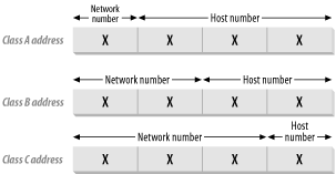
By convention, an IP address contains two components, as shown in Figure 1-1.
The first is the network number , and the second is the host number . Hosts that are on the same physical network normally share the same network number. There are five classes of IP address, indicated by the value of the first byte of the IP address:
- Class A
0 to 127: Each Class A network supports a maximum of 16,777,214 hosts. Though there are a total of 128 network numbers here, only 125 are usable.
- Class B
128 to 191: Each Class B network supports a maximum of 65,534 hosts. A total of 16,382 Class B networks are available.
- Class C
192 to 223: Each Class C network supports 254 hosts. A total of 2,097,150 Class C hosts are available.
- Class D
224 to 239: These networks are reserved for multicast addressing, which supports broadcasting the same data to multiple hosts.
- Class E
240 to 254: These networks are reserved for experimental use.
The following IP address ranges are reserved for special purposes and hence are not used to assign to any host (for a complete list of special-use addresses, see http://www.ietf.org/rfc/rfc3330.txt?number=3330):
- 0.0.0.0 to 0.255.255.255
Broadcast addresses. These are used to send traffic to hosts on the current network.
- 127.0.0.0 to 127.255.255.255
Loopback addresses. 127.0.0.1 is used to loop back to the current host (so if you try to make a network connection to that address, you are talking to yourself).
- 169.254.0.0 to 169.254.255.255
Link local addresses. These are used for hosts that have to assign their own IP addresses.
Tip
The protocols used on the Internet are defined in a collection of notes called RFCs (Requests for Comments). For more information, see http://www.rfc-editor.org/.
The following IP addresses are reserved for private networks (such as a home network). These private networks can be configured to see the outside world (see Section 1.1.4 later in this chapter, as well as DHCP and NAT in Chapter 5) without letting the outside world see them:
10.0.0.0 to 10.255.255.255
169.254.0.0 to 169.254.255.255
172.16.0.0 to 172.31.255.255
192.168.0.0 to 192.168.255.255
Figure 1-2 shows the Network number and Host number used in each class of IP addresses.
If you have ever manually configured a computer for TCP/IP networking, two of the configuration values are the IP address and a number called a subnet mask. If your network uses automatic configuration (see the sidebar DHCP and NAT in Chapter 5), then the IP address and subnet mask are automatically assigned to your computer.
To calculate a
network number from an IP address, you
can apply the subnet mask to it using Boolean arithmetic. For
example, consider the IP address 192.168.1.2. This is a class C
network and thus the first three numbers represent the network
number. To derive the network number, we apply a subnet mask of
255.255.255.0 (or
11111111.11111111.11111111.00000000 in binary).
Performing an AND operation between the IP address and the subnet
mask gives:
      11000000 10101000 00000001 00000010
AND   11111111.11111111.11111111.00000000
=     11000000 10101000 00000001 00000000
=       192.     168.      1.       0
The result (192.168.1.0) is the network number.
Table 1-1 shows the default subnet mask for the
three classes of networks.
Tip
Subnets are sometimes specified using the network number and number of bits in the subnet mask. So, the Class C example in Table 1-1 with a network number of 192.168.1.0 would be written 192.168.1.0/24 because there are 24 bits in the subnet mask.
Subnetting can be a wasteful way to allocate IP addresses. Consider a company that has more than 254 hosts: in theory, they would need a Class B IP address. But a Class B address can support 65,534 hosts; any remaining IP addresses would go unused, wasting a limited resource.
Instead of using a Class B address, you can instead combine a few Class C addresses into a supernet. Suppose you have about 700 hosts. You would need to obtain three Class C addresses such as:
192.168.1.0
192.168.2.0
192.168.3.0
Each Class C address can support up to 254 hosts, so three Class C addresses are sufficient to support 700 hosts. But how do all the hosts know that they are in the same supernet? The answer lies in the subnet mask again. Let’s examine the binary equivalent of the IP addresses just listed:
192.168.1.0   11000000 10101000 00000001 00000000
192.168.2.0   11000000 10101000 00000010 00000000
192.168.3.0   11000000 10101000 00000011 00000000
The binary patterns are all similar up to the first 22 bits.
So our subnet mask now becomes 11111111 11111111 11111100 00000000, or 255.255.252.0.
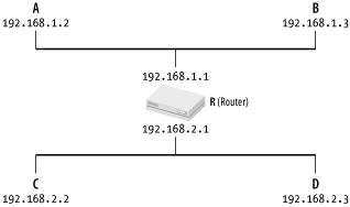
Let’s now discuss how data packets (short blocks of data used to transfer information) are transmitted between networks. Consider the first case where there are two computers on the same physical network (see Figure 1-3).
When A wants to send a packet to B, it first must know
B’s IP address (see Figure 1-4).
But to actually move data to B, A also needs to know the
Ethernet
address (also known as the MAC
— Media Access Control — address) of B. (An Ethernet
address looks like this: 05-EF-45-4D-2E-A5.)
To find out the Ethernet address of another computer, the
Address Resolution Protocol (ARP) is
used. ARP keeps a table containing a list of IP addresses and their
corresponding Ethernet addresses (you can list the contents of this
table by running the command arp -a at the Windows
XP Command Prompt). If the table contains the Ethernet address of B,
then A simply sends the packet over to B. If the table does not have
an entry, A broadcasts an ARP query (“Who has the IP
address 192.168.1.2?”) to all the computers in the
network. B will respond with its Ethernet address, which is then
stored in A’s ARP table. A can now send the packet
over to B.
What happens if A needs to send packets to another computer on another physical network? ARP can’t cross network boundaries, so a router takes care of moving data between networks (see Figure 1-4).
If A is sending packets to B, it does so using the method just described. If A needs to send packets to D, it uses the following steps:
A uses ARP to find R’s Ethernet address.
A sends the packets to R, but specifies D as the final destination.
R uses ARP to find D’s Ethernet address.
R passes the packet to D.
Note that a router has more than one IP address, since it is connected to multiple physical networks. So, A and B know R as 192.168.1.1, and C and D know it as 192.168.2.1.
If you want to watch ARP resolution in action, launch the Ethereal protocol analyzer (see Chapter 4) and do the following:
Select Capture → Start.
Select the network adaptor that is connected to the network you want to monitor.
Set the filter to arp and click OK.
Open the Windows XP Command Prompt, and run the command
arp-dip-address(whereip-addressis the IP address of the computer you want to connect to) to remove if from your computer’s ARP cache; this forces it to broadcast the ARP request the next time you try to connect.Ping the computer using
pingip-addressat the Windows XP Command Prompt.
When the ping
is complete, return to Ethereal, click Stop in the Capture window,
and examine the log of ARP requests in Ethereal’s
main window. You should see the request and response, assuming that a
computer with the ip-address exists on
your local network and is
currently
up.
Identifying
computers on the network (and on the
Internet) by IP address is not particularly human-friendly. Just as
you are addressed by your name (rather than your Social Security
number), computers on the Internet are commonly addressed using
domain names
. Some examples of domain names are
www.amazon.com,
www.google.com, and
www.oreilly.com.
Instead of using IP addresses, we use domain names that are meaningful and easy to remember. A DNS server is a database that contains the list of IP addresses and their corresponding domain names. Because the database is huge, it is not practical for a single machine to host all the domain names. Hence DNS is inherently distributed — there are many DNS servers on the Internet, and each of them can turn some of the world’s domain names into IP addresses.
When you type www.oreilly.com into your browser,
your computer first obtains the IP address of
www.oreilly.com by querying a DNS server
(usually your ISP’s or
organization’s DNS server). If that DNS server does
not contain an entry for the domain name, it then looks it up on
other DNS servers that may contain an entry for
www.oreilly.com. Ultimately one of these servers
will find the IP address; if not, you’ll get an
error message.
The current version of IP addressing is Version 4, or IPv4. IPv4 uses 32 bits for addressing. If all the possible addresses are allocated, there would be at most 232 hosts, which is about 4.3 billion (4,294,967,296) addresses (not forgetting that a portion of these addresses are reserved for special purposes). Even with 4.3 billion addresses, it was estimated that we would still run out of IP addresses by the year 2008 (or the year 2028, depending on whose estimates you are looking at).
Though many schemes have been devised to prolong the “life” of IPv4, such as supernetting and Network Address Translation (NAT; see DHCP and NAT in Chapter 5), the industry is looking towards using IPv6, which supports 128-bit addressing (2128 different addresses).
Get Windows XP Unwired now with the O’Reilly learning platform.
O’Reilly members experience books, live events, courses curated by job role, and more from O’Reilly and nearly 200 top publishers.


