Market forces have brought conventional wireless hardware down to unbelievably low prices in a very short time. At the time of this writing, the average 802.11g access point or wireless router costs less than $60, and prices continue to drop. These inexpensive devices are making it easier than ever for the average person to quickly set up their very own wireless network.
But what can you do with wireless hardware once you bring it home? As it turns out, quite a lot. You can replace the antennas and wireless cards to increase wireless transmission power, and build your own access point with off-the-shelf radio cards and hardware. In this chapter, you’ll find all these hacks, as well as a number of hacks involving other types of wireless hardware.
Improve the range of your laptop with an add-on antenna.
Possibly the most frequently asked question at any wireless user’s group is “How can I make it go farther?” The single most effective means for increasing your range is to add antenna gain. Most people think of adding an external antenna to their access point, or replacing the existing antenna with one of higher gain. While this can help all of your wireless clients, most people ignore the need for a good antenna on the client side. While some laptops (such as the Apple iBook and Sony Vaio, to name two) ship with antennas embedded in the laptop screen, many people are using add-on wireless cards.
These cards leave an annoying little lump sticking out of the side of the laptop, parallel with the keyboard, and very close to the tabletop. This is the laptop’s only antenna, and in many cases, you can greatly improve performance by adding an external antenna.
Not all wireless cards accept external antennas. Some have removable antennas, allowing removal of the little plastic lump, and will accommodate two external antennas using pigtail adapters [Appendix A]. Others have no internal antenna at all and work only with an external antenna.
Here’s an incomplete list of PCMCIA wireless cards that accept external antennas:
Adding an external antenna to your laptop has two important effects. First, external antennas have much higher gain than the tiny dipole antennas contained in most wireless cards. Second, and possibly even more important, an external antenna brings the signal away from the desktop and the body of the computer, giving it more visibility, and making it easier to adjust the antenna to find the best possible signal.
While adding a proper external antenna will almost definitely increase your range, not all antennas are especially convenient. Here are three popular antennas that are quite small and unobtrusive.
HyperLink Technologies sells a 3.5” square, 8dBi patch antenna. It is small enough to Velcro to the back of a laptop, but it offers surprisingly high gain for the size (and price). It sells for $30 and is offered with a variety of connectors for different models of PCMCIA cards. You can find it online at http://www.hyperlinktech.com/web/re09p.php. A patch antenna is a directional antenna, with horizontal and vertical beam widths of 30 degrees.
If you use a Lucent/Orinoco/Avaya/Proxim card (or a derivative, such as the AirPort), then you might have seen the Orinoco Range Extender. It is way overpriced, selling for about $65. It looks like a rectangular white popsicle stick with a heavy rubber base and long feed line, and is advertised as a 5dBi omnidirectional antenna. The Range Extender is available from http://www.proxim.com/products/all/orinoco/client/rea/index.html.
You can find a nearly identical version from HyperLink Technologies (http://www.hyperlinktech.com/web/re05t.php), which is much more reasonably priced at $15. As with the patch antenna, your main advantage is the ability to purchase the antenna with appropriate connectors for a variety of PCM-CIA cards.
If you need more gain, one of our antenna designs [Hack #83] works quite well with the popsicle stick antennas. The base is nice for sticking the antenna on a nearby table or shelf, but best of all, it is easily detached from the antenna. The stick on its own is portable and, like the patch, is well suited for a slab of Velcro on the back of your laptop LCD. Some antenna hackers have cracked it open, trimmed and resoldered the feed line, and glued it back together again to make the perfect length of wire for their laptop size (and cut down on unnecessary cable loss).
Finally, if cost is an issue, you might consider recycling a discarded rubber ducky antenna from a WAP11, WET11, Cisco 350, or other access point. These are small, rugged black omnis or dipoles that offer 3 to 5 dBi gain. Some antennas even sport right-angle elbows.
A simple adapter or pigtail will let you use these low-gain antennas with your laptop, which is certainly better than leaving them to collect dust in a drawer. Pick a pigtail with as much flexible feed line as you need, and connect it to your laptop card. As always, be sure to check on the type of connectors you need for both ends of the pigtail (both the laptop card and the antenna will have unusual connectors). When in doubt, see Appendix B, or check the manufacturer’s specs online.
Use one of these popular embedded PC boxes as a building block for your access point project.
There is a huge variety of PC-compatible hardware available that is perfectly capable of serving as an access point. If budget is a concern, you can certainly pull out that old PC that is collecting dust in the closet, provided that it is roughly of 486/50 vintage or so. 386 machines, while nostalgic, are too painfully slow to deal with by today’s standards. Some people choose to use a full-blown tower case with an old 486 or Pentium processor as a combination access point and file server.
If you are planning on building out a large network project, it is advisable to standardize your hardware platform. This is a good idea from an aesthetic point of view, as well as for reliability and ease of troubleshooting. While your dusty old 486 might be just taking up space, brand new embedded machines are coming down in price. These are tiny, fanless machines that are designed to run on DC power and boot from cheap compact flash RAM. This means no moving parts, simple ventilation requirements, and potentially very long uptimes.
Not all embedded solutions are necessarily cost effective. One notorious example is the PC/104 hardware used in industrial embedded applications. Although it offers relatively low performance, this hardware has a reputation for robustness and ease of programming, as well as the standard PC/ 104 stackable bus. But even its extreme popularity in the industrial world hasn’t done much to bring down its price, relative to what is available in the general-purpose computing world.
Whatever hardware platform you choose, be sure that it meets your needs. When choosing a piece of hardware, you should remember to consider the number and type of radio and network interfaces, cooling and power requirements, size, RAM and CPU available, and of course, cost. Here are a number of solutions that DIY networks have found to bring a high performance-to-price ratio:
- Linksys WRT54G (http://www.linksys.com)
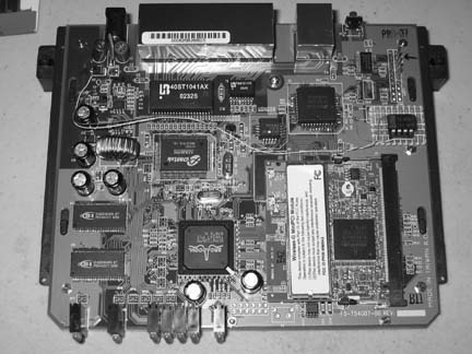
This might be the ultimate hackable embedded system. Linksys has released this wireless router in a number of flavors including the WAP54G access point, and the GS series with more onboard RAM and faster processors. Inside is a Broadcom CPU and radio, and out of the box it runs a custom 2.4 Linux kernel. You can pick up new WRT54G units online for around $50. There are also models from Asus, Buffalo, and Netgear with nearly identical internals. You can do a lot of hacking with the WRT54G, including running custom Linux images [Hack #67] and setting up mesh networking [Hack #68] .
Figure 4-1 shows a WRT54G Version 1.0 that has been taken apart. The operating system was corrupted while being hacked, and the box would not boot. A serial port has been soldered on to get a console and interrupt the boot process.
- Soekris (http://www.soekris.com)
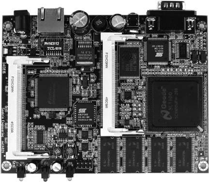
Affectionately known as the “little green box,” Soekris boards (shown in Figure 4-2) are a popular choice among do-it-yourself networkers. They are manufactured by Soekris Engineering in Santa Cruz, California. There are a number of Soekris models that work well as access points, with and without PCMCIA. All Soekris boards will boot from Compact Flash or the network via PXE. Most come standard with multiple Ethernet interfaces, a mini-PCI slot, hardware watchdog, serial console, and various processor speeds. They are all fanless boards and use a DC power supply.
One popular model is the tiny Soekris net4826. It provides one Ethernet port, two mini-PCI slots, USB, a 266 MHz Geode processor, 128 MB RAM, 64MB of integrated flash memory, and can be powered via Power over Ethernet. Most Soekris motherboards sell for $150 to $200. Unfortunately, although the green metal Soekris case might be unique, it isn’t watertight. If you are looking for a weatherproof Soekris kit complete with radio cards, mounting and pigtails, take a look at Metrix Communication (http://metrix.net). Metrix kits can accommodate up to two radio cards and pigtails, and come pre-installed with an updated version of Pebble Linux [Hack #70] . Metrix also offers discounts for community networking projects.
- WRAP (http://www.pcengines.ch/wrap.htm) and Mikrotik (http://www.mikrotik.com/)
Two other embedded boards that are currently popular are the WRAP by PC Engines and the Mikrotik RouterBOARD series. Like the Soekris embedded boards, these are general purpose motherboards that use very little power and can run a variety of operating systems. The WRAP.2C sports a 266MHz AMD processor, Ethernet, Compact Flash slot, and two Mini-PCI slots. The RouterBOARD 200 series is similar, and also includes PCMCIA support. Mikrotik also makes a commercial operating system that requires various licenses depending on functionality, but their boards will happily run Linux or BSD. WRAP boards cost around $175, while the RouterBOARD 200 series runs anywhere from $300 to $500. Mikrotik seems to be moving away from the DIY approach, and now offers a full line of rather expensive networking solutions.
PC Engines has its headquarters in Switzerland, while MikroTik is located in Latvia. Where they are available, these boards work quite well as wireless routers.
- Via-based computers (http://www.via.com.tw)
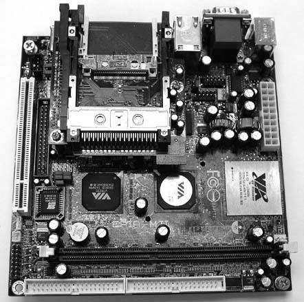
There are a number of Via-based computers on the market. They are generally marked as desktop PCs, although small, fanless cases that take a DC power supply are becoming commonplace. As they are intended to be used as general purpose PCs, they typically have 500 MHz or better Via processors, on-board NICs, an IDE interface, USB, and a PCI slot. Even better is the MII series of motherboards, which include a CompactFlash reader as well as a Cardbus/PC card slot.
If you are looking for a fanless solution, be sure to get the 600 MHz version, because the 800 MHz and faster Via boards require a processor fan. A Via MII-6000E fanless motherboard (shown in Figure 4-3) without case, RAM, or storage, costs around $170 at the time of this writing.
- The Fujitsu Stylistic series
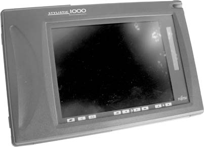
This collection simply wouldn’t be complete without mentioning the Fujitsu Stylistic 1000 series, shown in Figure 4-4. This is a popular surplus market tablet PC that has “hack me” written all over it. It has three PCMCIA slots, one of which is the boot device. It can boot from Compact Flash using a CF to PCMCIA adapter, and is unique in that it has an integrated LCD display and battery. The 1000 series has a 486 DX4/100 processor, is expandable to 40 MB RAM, can use a cordless pen for input, and has served just fine as a hardware gateway (I use one myself for my node on SeattleWireless). Fujitsu still makes the Stylistic series, although new machines are quite expensive (on par with modern laptops). The older 1000s or 1200s can frequently be found on the surplus market for less than $100.
Running your own custom access point can be considerably more challenging than the plug-and-play devices you can buy in consumer electronic stores, but building such devices can be much more rewarding as well. Bringing the power and flexibility of Linux or BSD to the access point itself can lead to all sorts of interesting possibilities that just can’t be accomplished with most over-the-counter access points. For details on how to get your own Linux-powered access point set up, see “Build Your Own Access Point with Linux” [Hack #63] .
Make your own tiny hard drive with no moving parts and low power consumption.
One challenge when building your own embedded wireless device is finding enough storage for the operating system and any data you need to keep track of. While 2.5” laptop hard drives probably have the highest ratio of storage space to physical space, they introduce a couple of challenges for an embedded system. A hard drive is a mechanical device, with fairly strict environmental operating conditions (for both temperature and humidity). They generate noise, draw a fair amount of power, and above all, are quite fragile. In other words, you probably wouldn’t want to consider leaving one in a relatively unprotected plastic box on your roof through the winter or summer.
A popular alternative to traditional hard drives is to use flash RAM instead. Flash memory uses only a tiny fraction of the power that a hard drive uses, and it can operate over a much wider range of environmental conditions. It is tiny, lightweight, and noiseless. It can be rewritten many thousands of times, and can even be dropped on the floor without fear of loss of data. While it isn’t nearly as cost effective in terms of price per bit, the popularity of digital cameras has driven flash memory prices down remarkably. If your application can fit in 32MB to 2GB of space, then flash storage is a viable alternative to 2.5” hard drives.
Many types of flash media can be used as a standard IDE device by using a simple converter, shown in Figure 4-5. One device I particularly like to use is the CFADPT-CS from Mesa Electronics. Their memory devices are available online at http://www.mesanet.com/diskcardinfo.html. It can be used on a standard IDE chain or with the SFF IDE found in laptops and embedded devices. As the SFF IDE bus provides power on the data cable (standard IDE doesn’t), you’ll need to connect a spare floppy power connector to the adapter when using it with standard IDE.
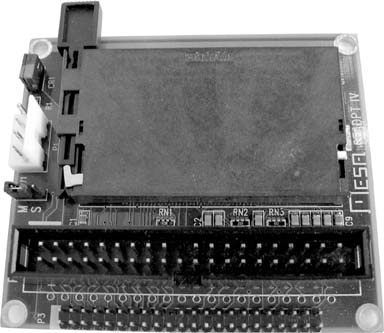
Once a CompactFlash card is inserted into the IDE adapter and attached to your computer, no further configuration is necessary. CF drives require no special drivers, and appear to be standard IDE devices to the host computer. Partition and format them as you would any other IDE device. Once an OS is installed, you can even boot from them.
Mesa also carries hard-to-find SFF IDE ribbon cable with connectors installed for a reasonable price—just ask. A number of suppliers carry CF-to-IDE adapters, and the going rate is about $20. While SmartMedia and Memory Stick adapters are also available, CF-to-IDE tends to be the cheapest way to go.
At the time of this writing, 512MB compact flash cards are available for under $40, 256 MB cards are available for around $25, and 128 MB cards are going for an unbelievable price of under $20. These are ideal for running a micro distribution, such as Pebble [Hack #70] or m0n0wall [Hack #71] . Note that while you won’t need one of these for use with the Soekris [Hack #53] as it boots from CF directly, these adapters will allow any computer with an IDE interface to eliminate its most unreliable component: the hard drive.
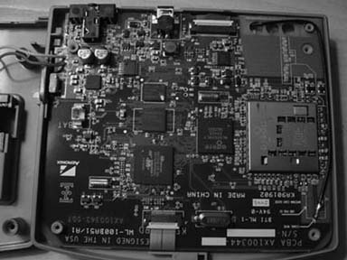
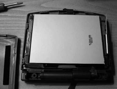
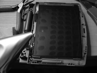
Radio waves don’t penetrate metal well, but that shouldn’t keep your PowerBook from getting online.
Apple’s PowerBook is arguably one of the most aesthetically pleasing laptops on the market. Its wide-screen display is particularly striking, and like the rest of Apple’s entire line, it can accommodate a built-in AirPort card. Unfortunately, while the choice of titanium or aluminum for an outer shell might make the PowerBook pleasing to the eye and touch, it wreaks havoc with wireless.
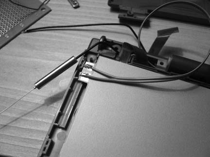
The all-metal case acts as an effective Faraday cage, blocking radio signals from anywhere but the tiny plastic antenna ports on either side of the keyboard. To make matters worse, the antenna ports coincide with the exact position that most people rest their hands when not typing. When this happens, it’s all too common for connectivity to drop altogether as the client radio desperately tries to find a path to the access point (AP).
Apple made a stab at solving the problem with the latest PowerBooks, which have an aluminum skin instead of titanium. The properties of aluminum are such that the interference decreased, but did not go away. Some users report increased coverage simply by making sure that the antenna connector is firmly seated in the AirPort card, as it can sometimes become dislodged slightly after leaving the factory. But even with a perfectly operating card and antenna, PowerBooks routinely see about half of the range of the cheaper plastic iBooks, which have a much more visible internal antenna.
Fortunately, there is hope. Since the PowerBooks have a PCMCIA slot, it is perfectly possible to add another wireless card and use it instead of the builtin AirPort. The biggest drawback to this approach is that Apple’s nicely integrated wireless tools work only with the internal AirPort card, so you will have to get used to using other means to control your wireless connection. But the two- to four-fold increase in range can be well worth the effort.
The WirelessDriver project lives on SourceForge at http://wirelessdriver.sourceforge.net. At the time of this writing, it is confirmed to support more than 40 different wireless cards under Mac OS X, and probably supports many more. It works with Prism-based cards as well as Hermes and Aironet cards. The software is available in a disk image installer, so no compilation is needed.
One popular add-on card is the EnGenius/Senao series, particularly the 2511. It puts out 200mW and is a particularly sensitive radio. It comes in two versions, with and without an internal antenna. If you use the 2511-CD+EXT2, you need an external antenna, such as an 8dBi patch [Hack #52] , as it has no internal antenna of its own. A good choice for a card with an internal antenna and an antenna connector is the Lucent/Orinoco/Proxim Silver or Gold card. Like the internal AirPort card, it puts out only 30mW, but is fairly sensitive, and quite inexpensive, averaging about $30 at this point.
Remember that the best thing you can do to improve the range of any wireless device is to make its antenna as visible as possible to the access point you are trying to communicate with. While an add-on card might not be as convenient as the built-in AirPort card, anything is better than hiding your antenna behind a suit of armor.
Power your access point without a separate power cable by using free pairs on CAT5.
A number of access point manufacturers (Proxim, Symbol, and D-Link, to name just three) are now offering Power over Ethernet (PoE) add-ons for their access points. PoE modules insert DC voltage into a standard Ethernet cable. The idea is to supply the AP’s power and UTP Ethernet connectivity requirements via a single Ethernet cable.
This works great in areas where you might not have power easily accessible, such as a roof. This also allows you to more easily place the AP closer to the antenna, thus reducing signal loss over antenna cabling. Ethernet signal travels well over CAT5 cable; a 2.4 GHz signal doesn’t do as well over antenna cabling. Also, Ethernet cabling is much cheaper than antenna cable such as LMR400. This hack demonstrates how to build a simple PoE module pair.
In June 2003, the IEEE ratified the 802.3af standard for Power over Ethernet, which has spurred the release of standards-compliant PoE products. 802.3af defines two types of power source equipment: end-span and mid-span devices. An end-span device is an Ethernet switch with embedded PoE technology. These switches deliver data and power over the same wiring pairs: 1/2 and 3/6.
We’re going to build a pair of mid-span devices, which in the 802.3af specification can be placed between a legacy switch and the device to be powered. A mid-span device has an RJ-45 data input and a power input, and it sends the data on pairs 1/2and 3/6, while sending power on the unused 4/5 and 7/8 pairs.
If you have a device such as a VoIP phone or a Soekris PC that will accept Power over Ethernet without a secondary adapter, you will only need to build the power injector in steps 1–3.
Warning
Don’t try this unless you have some knowledge of electricity. 12v isn’t going to kill you, but you might cause serious damage to your access point and other equipment.
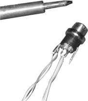
Solder wires to the DC Male Power Plug. Solder one pair (two wires twisted together) to the inner-contact connection. These will be the positive power wires. Solder another pair to the outer-contact connection. Notice that there are three connectors on this DC male power plug. One is for the center pin, one is for the outer surface, and one goes to the plug housing. You do not need to solder anything to the plug-housing connector. Figure 4-6 shows what it should look like when finished.
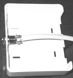
Drill a hole in your two-port mount housing. Mount the male DC plug in the housing, as shown in Figure 4-7.
Connect the wires in your two-port jack as follows:
Wire the one port wall mount jack as follows:
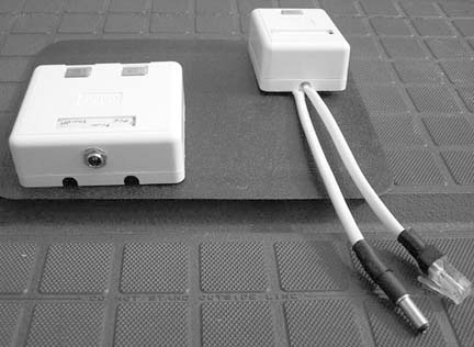
Plug in and test. Figure 4-8 shows the completed modules.
The DC resistance of CAT5 is about 3 ohms per 100 feet per conductor, so a 250-foot cable has at least 7 ohms resistance. Most of the time, an AP draws much less than 0.8A, so you would still be above 6V at the AP. In fact, the access points typically use linear regulators to drop the voltage down to 5V on their insides, so as long as you’re giving them something better than 6V at the terminals, they’re likely to work.
There is a good calculator online at http://www.gweep.net/~sfoskett/tech/poecalc.html that calculates the voltage drop for a given length of CAT5. Use it to estimate how much power you need to provide at one end of your cable run in order to power your access point.
—Terry Schmidt
Put your AP where everyone can see it: on the ceiling.
Back in May 2003, some friends and I were hanging out at a really good coffee shop in Sebastopol, CA. This particular coffee shop is housed in an old wooden train station building, with high ceilings, old-style hanging industrial lamps, and even a couple old trains still on the tracks, serving as small businesses.
Unfortunately, there’s no wireless available at this shop. There was, once upon a time, back when the O’Reilly offices were located across the street. But that was ages ago, and even then the signal wasn’t all that it could have been. As we sat around drinking our high-octane beverages, we got to talking about the best way to provide coverage in such a huge space. The room we were in was a common room, open at all hours (the front entrance is huge, and doesn’t even have a door.) While you could put an access point in one of the enclosed shops in the building, coverage in the open area would likely be spotty at best. You would want the AP to be located high up off the ground, where everyone could see it.
Almost simultaneously, we all looked up and noticed the lamps hanging from the wooden rafters. What if you could house an AP in a package the size of a large light bulb and install it in an existing light socket? This seemed like a good idea, but how would you get network access to it without running CAT5 to the socket? Easy: Powerline Ethernet.
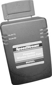
With the recent release of the Siemens’ SpeedStream series of tiny access points and other Powerline Ethernet devices, such an insane, caffeine-induced idea as an AP in a light bulb might be a possibility. These devices are quite small, about the size of a standard wall wart, as shown in Figure 4-9. They sport a Compact Flash wireless adapter that acts as the AP. It’s the same card as the popular Linksys WCF11 but with a different sticker.
The brilliant bit is that the wireless network bridges directly to the AC power, so a standard Powerline Ethernet adapter anywhere on the same power circuit can provide Internet access to as many APs as you care to plug in. At a mere $85 retail, we couldn’t resist picking one up and seeing what we could do with it.
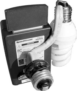
One of our first concerns was practical rather than technical. Obviously, if you’re going to replace a light bulb with an access point, the room will likely get darker. That is, unless the AP can also provide light as well. After fooling with a couple of lighting ideas, we finally soldered some copper romex onto a fluorescent bulb as a prototype. The romex is rigid enough to hold the lamp steady, and easy to solder. The fluorescent bulb would obviously be dimmer than a 300-Watt spot lamp, but it would be better than nothing. And as a flourescent runs much cooler, it probably wouldn’t turn the guts of the access point to liquid. This solved the light issue well enough for the moment, but how could we connect the whole thing to a standard light bulb socket?
One trip to the hardware store later, we had a variety of Edison plugs, sockets, and adapters. We settled on a simple extender type of device, with a female socket on one side and a male plug on the other. Again, the contacts were copper, making it easy to solder on more romex, as shown in Figure 4-10. We had the basic design together, but what could we possibly use for housing?
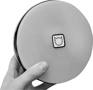
Tupperware, of course. Adam painted the inside of a Tupperware bowl white, and the entire device just managed to squeeze inside. We first attempted to take the SpeedStream unit apart to save space, but it’s already tightly packed inside; much of the unit is occupied by a large transformer. Besides, keeping the original enclosure made us all feel a bit more relaxed about plugging the thing in. The Edison plug poked through the bottom of the bowl, where we simply screwed on another connector to keep it tightly attached.
So, with all of the technical considerations accounted for, all that was left was the all-important marketing phase of the project. Some electrical tape and one vinyl sticker later, the NoCat Night Light was born! See it in all of its glory in Figure 4-11.
But how well would it actually work? Wouldn’t the fluorescent throw off all sorts of noise that would interfere with the AP? We certainly thought so. Unfortunately, we didn’t have a machine handy with which to do real throughput testing, but DSL Reports (http://www.dslreports.com/stest) showed a very respectable 2Mbps or so. This was well above the rated capacity of the cable modem network we were using, so we were definitely satisfied with the results.
One big improvement to the design would be to replace the fluorescent bulb with a bright LED array, or even a simple socket so you could use whatever (low temperature) light source you like. Our design makes much more sense than Siemen’s original, as it gets the AP up off of the ground and above your head, where presumably many more people can see it. Adding more APs is as simple as screwing in a light bulb, as they bridge directly to the same AC Powerline segment, and terminate at the same Ethernet.
Keep in mind that this design is a prototype, and while it works in casual testing, it hasn’t been tested for hours of continuous use. At the very least, it would be a good idea to insulate the bare contacts and find a better way of ventilating the fluorescent bulb (or replacing it altogether with an LED array). Build it at your own risk, but by all means have fun while doing it.
—Adam Flaherty (Design/Fabrication)
—Rob Flickenger (Documentation/Production Assistant)
—Nate Boblitt and Roger Weeks (Idea Rats)
Significantly increase the range, sensitivity, and functionality of your WET11.
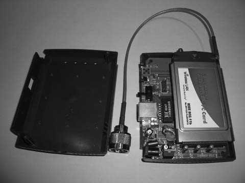
The Linksys WET11 (http://www.linksys.com/products/product.asp?prid=432) is one of the most inexpensive Ethernet client bridge products on the market. It works with virtually any Ethernet device, and doesn’t require any special drivers to configure. Many people use the WET11 to connect devices that otherwise can’t accommodate a radio with their wireless network. For example, they are ideal for connecting to networked appliances such as the PlayStation 2 or Xbox to avoid having to run Ethernet cable to your television.
Linksys has manufactured the WET11 for several years. Its popularity can be gauged by looking at the Linksys web page and noting how many other 802.11b-only devices are still being sold (hint: not many). It has a big brother called the WET54G, but it is expensive and is not hacked as easily as the WET11.
As with all embedded hardware devices (particularly those manufactured by Linksys), it is a good idea to keep up on firmware updates. Updated firmware usually resolves most flaky behavior and occasionally even gives you a couple of new features. Previous firmware updates have fixed problems with DHCP.
The WET11 even has a crossover switch for the Ethernet side, making it simple to install, regardless of whether you are using a straight-through or crossover cable. Its tiny size and simplicity make it an ideal component for any situation where you need to get an Ethernet device to act as a client to an access point.
A WET11 can also be used to get entire networks online when used in conjunction with inexpensive firewalls like the Linksys BEFSR41. Simply connect the WET11 to the WAN port on the firewall, and every device plugged into it can share the WET11’s wireless connection. People have had mixed results when using the WET11 directly bridged to a hub or switch, due to the implementation of the tiny device’s MAC address handling.
But these features aren’t nearly enough for wireless hackers. Here are a couple of nifty hacks for this piece of hardware.
The WET11 can easily accommodate an external antenna. Simply unscrew the small rubber ducky antenna and replace it with an RP-SMA pigtail [Appendix B] and an omni antenna of your choice. This alone significantly improves the range of the WET11 and, when using a directional antenna, can help reject noise and cause less interference for nearby networks. Save the discarded antenna for use in other projects, such as an add-on antenna for your PCMCIA radio card [Hack #52] .
Possibly the greatest drawback to the WET11 is the cheap radio card installed at the factory. It ships with a low-end, 80mW radio with less-than-average sensitivity. Fortunately, the card is based on the Prism 2 reference design. If you don’t mind voiding your warranty, you can upgrade the card to a much more sensitive, higher power Senao or EnGenius card. The Senao (or EnGenius) 2511 Plus EXT 2 is an ideal card, as it even uses the same internal antenna connector, making the upgrade easy. Before you proceed, upgrade the replacement card with the latest firmware. Details on upgrading Prism 2 firmware can be found at http://linux.junsun.net/intersil-prism.
Unplug the Ethernet and power from the WET11. Remove the rubber feet from the bottom of the WET11 and open the case. Carefully unplug the antenna connector, unscrew the card from the brass stand-offs, and remove the internal card. Unfortunately, you won’t be able to reuse the standoff screws, as the replacement card has a slightly different physical packaging.
Plug in the new card, and reconnect the antenna cable to it. If the PCMCIA card is oriented with the antenna connectors toward the right (and the Senao/EnGenius label is facing you), you want to use the connector on the top. This is the same side that was connected to the original card.
Finally, reassemble the case and power it up. You should now be enjoying the benefits of a much more sensitive radio and a full 200mW of power. Figure 4-12 shows an open WET11 with a Senao 200mw radio card and pigtail.
The WET11 is expecting a 5V DC power source. A number of people have reported success using the WET11 with a battery pack in the field. Using four NiMH batteries in a series (at approximately 1.2V each) yields a 4.8V battery, which seems to work fine for several hours with the WET11. The WET11 can accept voltages a bit higher than 5 volts (some say as high as 12V), so you could even theoretically use four Alkaline batteries (4 x 1.5V = 6V). If you make your own battery pack, be sure to observe the proper polarity! Also note that operating time will likely be significantly shorter if you transmit a lot and use the 200mW card as described previously.
An external battery pack can be handy for generating a signal source when doing a site survey, or for hiding a signal source in a game of wireless hide-and-seek. There is a detailed discussion, with photos, online from a Belgian site at http://reseaucitoyen.be/?SourcePortable (be warned; the entire site is in French). With the size and ubiquity of the WET11, it’s no wonder that so many people are hacking on it.
Build yourself a motorized scanner that shows you all wireless networks in 360 degrees.
If you’ve done any number of wireless surveys, you know that one of the most time-consuming parts of the survey is moving the antenna. This is especially true if you are working with highly directional antennas. Sometimes, you might not have another person with you to move the antenna and take signal measurements.
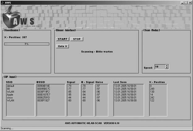
The Automatic WLAN Scanner (AWS) is designed to help with these problems. It will perform a 360-degree scan for wireless networks and then give you the SSID, signal strength, noise, and best antenna position for all discovered networks.
An AWS can be built inexpensively. For my prototype system, I used a number of components, many of which were scavenged from old computers or from second-hand electronics stores. You will need:
Hard disk frame from an ATX case
AC/DC wall-wart power supply
Standard ATX power connectors
Flat-bed scanner
Reverse-SMA microwave connector
Screws
Hot glue gun
Stepping motor
Cantenna [Hack #86]
Orinoco 802.11b wireless card
Antenna cable & pigtail
SMC800 Stepping motor steering card
Ball bearings
Worm drive
Cog-wheel or toothed wheel
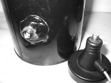
You could build the cantenna by following the instructions in “Pirouette Can Waveguide” [Hack #86] . However, I’ve made a modification to the design, as shown in Figure 4-13. I disassembled an omni antenna with a magnetic base. At the top of the magnetic base is a female Reverse SMA [Appendix A]) connector. Therefore, I constructed the cantenna with a male Reverse SMA connector, so that the cantenna easily screws onto the magnetic base.
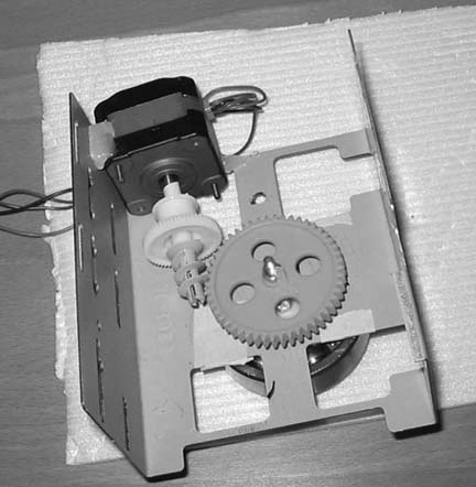
Once you have completed the cantenna, the next step is to build the base, which will house the motor, worm gear, cog-wheel, and ball bearings to drive the cantenna. Figure 4-14 shows an overview of the assembled base, turned upside down. I used a hard drive frame from an ATX computer case, but you could cut your own sheet metal as well.
As you can see, placement of the motor is critical. You will want to first get the cog-wheel installed using a long bolt and nuts, and connect the bolt to the ball bearing on the other side of the base, as shown in Figure 4-15.
Now that the cog-wheel and ball bearing are in place, attach the worm drive to the motor shaft and experiment with the best placement for the motor. When you find the best place, make sure to mark it clearly on the base so you don’t lose the location. Next, use the hot glue gun to hold the motor in place on the metal hard disk frame.
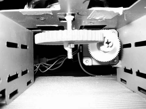
With the base constructed, you can now turn it over, as shown in Figure 4-16. The ball bearing will rotate under command of the stepper motor and worm drive, and the magnetic base of the antenna will hold the can firmly in place while the motor turns.
I chose to house the SMC800 card in a small metal tin, which gives the card protection when the lid is closed. One end of the tin is cut out to allow connection of the parallel cable to the SMC800. In the other end of the tin, I punched a small hole for the power cables. The three power cables from one side of the ATX power cable were ran through the tin and connected to the SMC800 card pins that drive the external motor, and the other side of the connector was wired directly to the motor.
Power is supplied to the SMC800 card using an external AC/DC adapter. Prior to the installation of the card in the red tin, I made a third hole to allow insertion of the power adapter to the card. Figure 4-17 shows the power and data connections to the card.
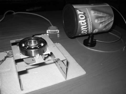
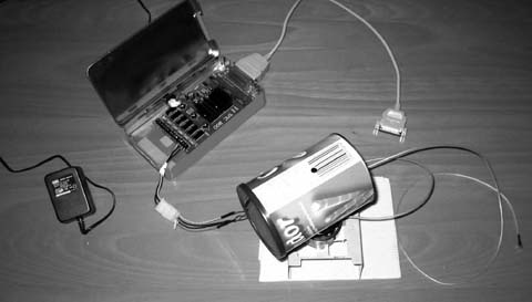
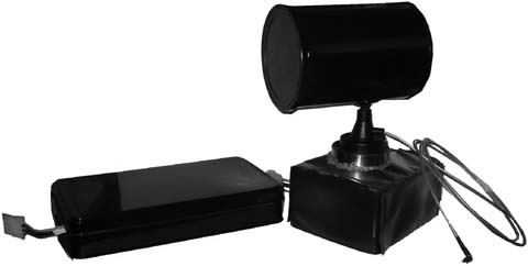
The hardware construction of the AWS is complete at this point. For my finished unit, shown in Figure 4-18, I spray-painted the tin and the cantenna and enclosed the base in waterproof vinyl. Lastly, I sealed the area between the ball bearing and the vinyl with hot glue.
The SMC800 is an old card that has only DOS drivers available. Since my project relies on NetStumbler [Hack #24] to discover the wireless networks, I had to write new Windows XP drivers for the SMC800. These drivers, along with the other software I wrote for the project, are all available on my web site at http://aws.netzfund.de.
The second necessary piece of software is a Visual Basic script, which runs under NetStumbler and reads out the necessary wireless data.
The third piece is the AWS control software, which uses the new driver for the SMC800 to control the card over the parallel interface. Using the software, you can set your own scan speed, depending on your requirements. You can also start and stop the scan, and then go to a specific stepping position on the motor.
The AWS software receives input from the Visual Basic script running with NetStumbler, and shows the data as it is received. Figure 4-19 shows the AWS software up and running.
The next feature that I plan for AWS is a position-locating system, so that AWS will steer the antenna in real time to follow a moving wireless source. Obviously, one limitation of the AWS as built is that it is capable of scanning only on a single flat plane. In order to scan above or below the horizon, you will need a variable mount for the cantenna.
—Marcel Bilal
Add a backlight to this tiny wireless communicator, so you can use it in the dark.
The Zipit Wireless Communicator (http://www.zipitwireless.com) isan amazingly cool, cheap wireless handheld device that has just one purpose: 802.11b communications. It’s marketed primarily to teens as an instant messaging device, but guess what? It also runs Linux on an ARM chip and uses an Orinoco radio card. It has a tiny 16MB of RAM and a scant 2MB of flash memory, making it difficult (but not impossible) to run applications on it. There are a number of ways to get Linux running on the Zipit [Hack #73] .
There’s one thing the Zipit does not include: a backlight. It’s really a shame that manufacturers continue to ship devices without a backlight; it’s often the kiss of death for products that otherwise might develop a following.
To add a backlight, you’re going to need an electro-luminiscent (EL) panel. I found a suitable piece of EL panel for this hack at Miller Engineering (http://www.microstru.com). Secondly, you’ll need a driver chip to make the EL panel work. I found a chip already mounted to a tiny board from Jelu (http://www.jelu.se/shop/product_info.php?cPath=1_29&products_id=33).
Here’s a step-by-step account of how I added the backlight. No, I won’t buy you a new Zipit if you break yours while attempting this.
Flip the little guy over. Unscrew the battery cover and yank the battery. Pry up the tiny rubber feet to reveal four Phillips-head screws, as shown in Figure 4-20.
Remove them. The entire bottom should come off easily. On my unit, the sticker covering the battery area was stuck to the CPU, so you might have to gently pry that up with a screwdriver. Be careful as you pull the bottom off, because the speaker is attached to a recess in the bottom with gummy glue. Pry up the speaker and completely remove the bottom shell.
Be careful not to lose the power button cover. Take it off and put it where you put the case screws (and don’t lose those either).
You’ll need a soldering iron for this step. First, apply heat to the antenna connector cable and remove it from the board. Next, lift the white part of the plastic LCD panel connector (it should swing away from the board) and gently remove the brown ribbon cable.
Put the mainboard and keyboard membrane aside. You can remove the rubber keyboard too if you like.
Open the Zipit lid, and remove the teeny rubber discs on the inside of the hinge. Remove the exposed Phillips-head screws.
Leave the Zipit open and flip it back over, as shown in Figure 4-21.
Near the brown LCD ribbon cable you should see three more Phillips-head screws. Two are connected to the metal pivot hinge. Leave those in place. Remove the third screw, which will release the small cap covering the ribbon cable and antenna feed. There was also a tiny pink plastic clip jammed into this space on my unit, putting pressure on the cables. Remove and discard it. Since we’ll be adding a power cable for the backlight here, you won’t have enough space for it, and since it just chafes the cables anyway, you won’t miss it.
Now, here’s the tricky part. Wedge a plastic screwdriver (or your thumbnail) between the two halves of the LCD side of the case and pry them apart.
Don’t use a metal screwdriver; if you do, you’ll leave nasty marks on the edge of the case. You have to pull pretty hard to unsnap the case, and directional pressure doesn’t really help. Just yank the thing and it’ll pop open.
Also, be careful when prying this apart not to lose the lid latch and spring. You can probably live without them, but if you want to keep them, now is your chance not to let them fly across the room or fall behind the workbench.
If all went well, you should see the white backing of the LCD panel, as well as more brown ribbon cable and the lid antenna, as shown in Figure 4-22. The white backing is held to the LCD with a sort of thick rubber cement. You need to peel this backing off and replace it with EL panel. The cement will stick to the LCD.
Pick at a corner of the backing with a razor blade (or a fingernail). Try to peel off the backing all in one piece, pulling firmly away from the LCD. Keep in mind that the LCD is made of glass and is very, very fragile. You also don’t want to touch the gummy cement with your fingers or any tools, since any marks you make in it will be visible when you install the backlight.
When the backing has been removed, it should look something like Figure 4-23.
You should now be able to estimate how much EL panel you will need to cover the LCD. Trim yourself a nice piece using a pair of scissors. It should overlap the LCD panel on three sides by a couple of millimeters. On the side nearest the antenna, leave one set of leads and trim off the rest, as shown in Figure 4-24.

Once you have trimmed the panel, place it gently on the LCD. I installed mine sort of like you install a piece of linoleum floor. You want to avoid air bubbles, so start in the middle and gently press the panel out towards the edges. Try to push any air bubbles all the way to the edge. If you trap a bubble, start over by pulling the panel all the way back off. This is easier than stripping the backing, since the panel is made of plastic. Remember, that’s delicate glass you’re pushing on, so don’t press too hard.
Solder a couple of wires to the leads on the EL panel, similar to Figure 4-25. I used ribbon wire salvaged from an old floppy disk cable. It should be at least eight or nine inches long, preferably stranded, and as thin as you can find (recycled CAT5 cable is way too thick). Remember that plastic will melt if you’re not careful with your soldering, so be quick.
Run this wire the same way the antenna wire is run. Cover the exposed leads on the EL panel with a piece of electrical tape.
Flip the Zipit back over, and put the mainboard back in place. Feed the antenna cable and the two wires through the hole closest to the LCD panel connector.
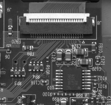
Now comes the fun part: soldering the leads to the mainboard, as shown in Figure 4-26. Attach one wire each to the plus and minus poles on the battery connector. Solder a third wire to the corner pin on RP4, on the R108 side closest to C116.
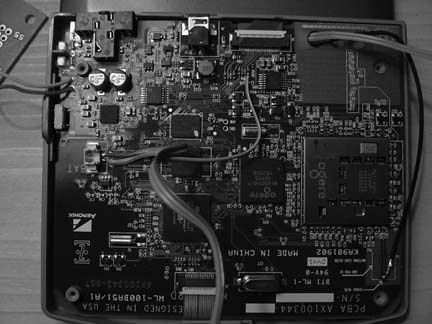
Figure 4-27 shows a detail with the proper pin labeled EN.
Finally, reattach the antenna lead. When you’re done, it should look like the unit shown in Figure 4-26. If your soldering iron isn’t fine enough to solder the third wire, don’t panic. This pin is pulled high when the LCD panel is active, so once we figure out power management on the board, this wire will turn the backlight on and off when the lid is closed. Of course, we haven’t figured out power management as of this writing, so the backlight stays on all the time anyway under Linux. If you’re running the Zipit messaging client, the backlight works beautifully and turns off to save battery time.
If you can’t get this wire attached without destroying the board, just connect that wire directly to power and the backlight will stay lit all the time. It’s not ideal, but it’s better than nothing.
Now, solder in the EL panel driver board. The driver board from Jelu is based on the Supertex HV857MG driver (it’s pretty much a nice little implementation of the reference design). I’ve noticed that this chip isn’t designed to drive a panel as big as the one for our Zipit, so it ends up being a mellow blue instead of bright white. If you change the chip to an HV826 or HV830, it should be much brighter. I’ll likely give that a try at some point. Figure 4-28 shows the finished unclosed case with a close-up of the driver board.
Connect LA and LB to your EL panel (it doesn’t matter which is which), and connect GND to minus, VDD to plus, and EN to the remaining wire. At this point, you probably will want to connect the battery and power up the Zipit to be sure that everything works as expected. Don’t touch the driver board while it’s on, unless you are partial to electric shocks for fun.
If all went well, completely cover the driver board in electrical tape and carefully reassemble the Zipit. There’s plenty of room for the driver board in the channel next to the battery compartment.
Congratulations! You can now use your Zipit in lighting other than direct bright sunlight!
Removal is the reverse of installation.
I’m definitely going to try a different EL driver chip to get the brightness up a bit. But the Jelu model should get you going. These things are really neat; you typically need a big, whiney transformer to drive EL, but these driver chips are small, quiet, and efficient. A tiny driver board combined with a light that you can cut with scissors to any shape should make it easy to add a backlight to just about any transparent LCD display.
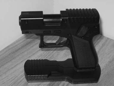
Why be stuck with a short cable when you can use Bluetooth in your pistol mouse instead?
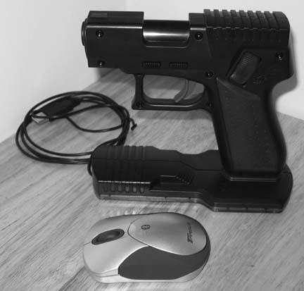
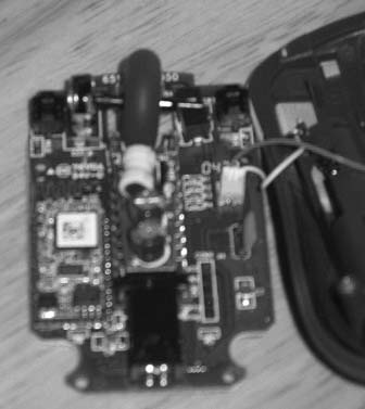
The PistolMouse FPS by MonsterGecko (http://www.monstergecko.com/products.html) is a great way to play first-person shooters. However, when you’re at a LAN party and you want to wave the thing around after fragging your friends, you are rudely reminded of the short USB cord handing from the front of the unit.
By taking the main board out of a Targus AMB01US Bluetooth Mini Mouse (http://www.targus.com/us/product_details.asp?sku=AMB01US) and replacing it with the main board of the PistolMouse FPS, you can make the MonsterGecko device wireless for use with any Bluetooth equipped system. Figure 4-29 shows the two mice, side by side.
First, get everything together, so you don’t have to make three trips to the local electronics store during the assembly process. Here’s what you’ll need:
22 +/- 2 gauge stranded wire
Heat shrink tubing for above wire
Solder
Liquid Solder Flux
Desoldering tape or desoldering tool
2 AA Battery Holder from Radio Shack (catalog # 270-408)
Philips screwdriver set
Hex screwdriver set
Soldering iron
Multimeter for checking continuity
Dremel tool or similar
Next, if you haven’t already, test out both the PistolMouse and the Targus mouse to make sure they both function properly with the system where you plan to use them.
If you have any questions during the project process, check my Flickr photoset at http://www.flickr.com/photos/_bt/sets/494023, which contains 21 pictures of the process (I obviously couldn’t include them all in this hack).
Disassemble the MiniMouse by removing the two small mouse feet stickers near the rear of the mouse. This will expose two screws. Remove these. Open the mouse and remove the battery cover. Then, remove the blue frame from the mouse, which is latched toward the front of the mouse with clips, as shown in Figure 4-30.
Be careful not to damage the MiniMouse main board during this process. There are two wires going to the main board, red and white, for power; just pull the plug out of the board and set aside. Remove the black housing over the LED on the back of the main board, because this is usually too large to keep in the finished device.
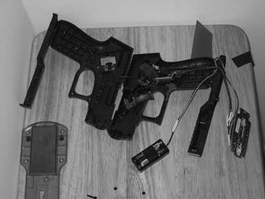
Disassemble the PistolMouse FPS with the Phillips screwdriver on the bottom and using a hex screwdriver on the sides. You will have to remove the red plastic grip (attached just with friction on the left side of the gun) to get to the hex screws. There are a total of 11 hex and 6 Phillips screws to remove from the PistolMouse. Be careful to keep track of any parts if they fly out during this step.
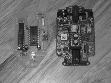
Remove the main board from the PistolMouse FPS and detach any wires and place to the side. You will need this for reference only, if at all. Figure 4-31 shows the MiniMouse board (on the right) and the much simpler Pistol-Mouse board (on the left).
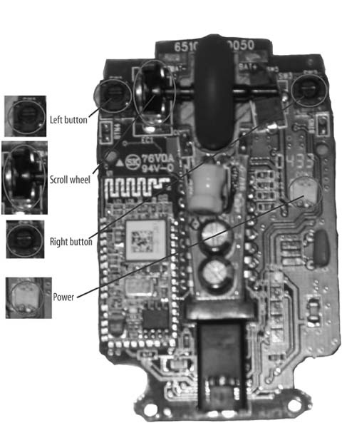
There are four sensors on the MiniMouse main board, which are highlighted in Figure 4-32. The left, right, and scroll wheel buttons, as well as the scroll wheel sensor, must all be removed. Remove these with any method you are comfortable with: either desoldering tape or a desoldering suction device. For your own reference, take note of the orientation of the scroll wheel sensor.
Now you will extend the wires from the original PistolMouse FPS to the MiniMouse main board, as shown in Figure 4-33. Use wire of more than sufficient length at this point; you can cut it short later. Use the heat shrink tubing instead of electrical tape for attractive wiring, as well as helping make it as small as possible.
Orientation for the following instructions is the front of the mouse and the rear of the mouse, as held in your hand.
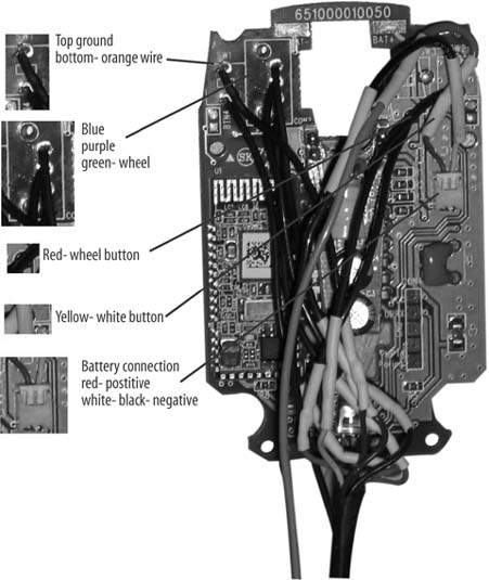
Please double-check the ground connections on your mouse before proceeding using the multimeter and the two connections for each button, in case Targus has changed the MiniMouse main board:
The left mouse button is wired, so the front solder point is going to the brown wire (which is ground) and the rear is going to the orange wire.
The scroll sensor uses the three solder points to the right of and between the sensor mounting points. From front to rear, use the blue, purple, then green wires.
The wheel button uses the front solder point; the rear is ground and already connected via the left button.
The right button uses the rear solder point, the front being the ground here.
Now, add an extension of wire to the AA battery holder, as shown in Figure 4-34. This will need to go from the top of the gun all the way to the bottom front. Attach the power plug to this extension so that it can plug into the MiniMouse main board.
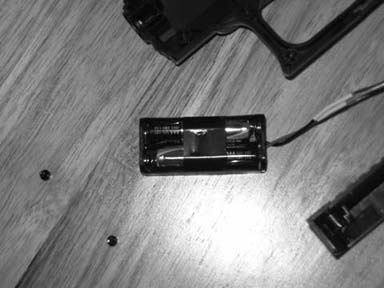
Put AA batteries in the holder and turn on the PistolMouse. As with Mini-Mouse in its original form, you might have to click the buttons a couple times to make sure the unit is on and working. Click or manually press the switches on the PistolMouse and verify that they are working on your system. At this point, you should have a disassembled working unit, like the one shown in Figure 4-35.
One problem I experienced was that I originally plugged the ground into a different point, and this gave a ghost of constant clicking on the left button. After connecting ground to the left button connector, the device worked fine. Test things like ground, to make sure they are all connected and do things like tracing the wires from where they are plugged in, to where they go to the buttons.
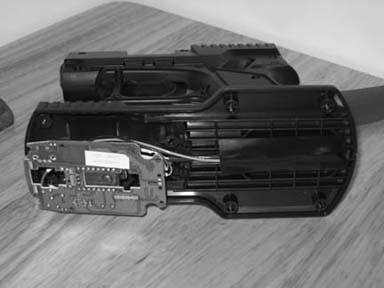
You’ll need to make room in the plastic of the PistolMouse FPS for the new larger main board. Use a dremel or similar tool to remove the fins in the black plastic where the board sits. You will also have to remove red clear plastic material from the bottom. In the end, the board should sit gently on the red plastic with the lens optic in place. The optic from the original board and the new one were exactly the same in my experience, so you can use this to assist in positioning the board in place. The extra wires you now have on the board will press it down in actual use. Figure 4-36 shows the bottom of the PistolMouse with the new board and the modifications I made.
You will also have to cut two small holes in the red plastic, as shown in Figure 4-37. One will be for the on/off switch. I did this in order to be able to use the switch from the original mouse, but I still have to use a paper clip to flip the switch. Do this carefully.
For the connect switch, you will have to carefully figure out where it is under the red plastic, then drill a hole so the connect button can be installed. I used a few layers of electrical tape to make the hole walls taller so the button wouldn’t come loose. Use incremental sizes of drill bits until the hole allows the button to be pushed and return to its place, but still tight enough that it won’t come loose during use.
Once everything is working properly, it’s time to reassemble the unit. Begin by putting fresh high-quality AA batteries in the holder, because they are not easy to replace. Then, put the holder above the scroll wheel in the cavity above the trigger. Run the wires for all the buttons and batteries down the front of the gun, so they don’t interfere with any other buttons or screw holes. Then, screw together the two halves and replace the rubber grip.
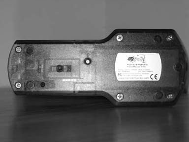
Put a piece of tape over the wires as they exit out of the top of the gun into the bottom, and make them run along the center channel on the bottom of the black plastic. Then, align the main board and optic on the red plastic and attach the bottom plate. Screw this on and everything should be together. Turn on the unit and test and debug further if needed. Often, you’ll need multiple attempts to run the wires smoothly and reassemble the bottom piece. Figure 4-38 shows the finished reassembled unit.
Use the new mouse as you would any Bluetooth device. It should work on both Macs and PCs that have Bluetooth. It should perform similar to the original PistolMouse FPS, since they both are 800dpi devices.
Warning
Do not remove or fail to put back in place the orange tip to the gun, because this signifies it as a toy weapon. If it is removed, there might be civil penalties, as well as a danger to yourself if you use the device in public.
Enjoy your new wireless Pistol Mouse, and play safe.
—Bryan Hurley
Why keep your wireless router in one place when you can give it wheels?
I’ve always thought that remote-controlled toy cars offer a great platform for other uses. For a while now, I’ve been thinking about how to put a small-form-factor PC motherboard on an RC car, but that would require quite a large car. When I stumbled upon OpenWRT [Hack #67] , I realized that the WRT54G provided wireless, processing, and general-purpose I/O interface capabilities in one small package! With a wireless router mounted on a Wi-Fi–controllable car, you can patch holes in your wireless coverage, drive the car from any Internet terminal in the world, or a variety of other things that I couldn’t think of right away. But I knew it would be cool. So I set off to mobilize my WRT54G.
There are two separate hacks that need to be done here: the software for the router, which will accept TCP connections and output the proper values to the GPIO pins, and the hardware, which will take those GPIO outputs and use that data to drive the car. Let’s start with the software.
OpenWRT is a minimal Linux distribution for the Linksys WRT54G. The router still works as a router, which I think is impressive, while allowing you to tinker with things such as adding an SD card reader, adding an LCD, or whatever you want. For my hack, I borrowed code from the LED System Load Monitor and the SD Card Reader, both found on the OpenWRT web site (http://wiki.openwrt.org/OpenWrtDocs/Customizing). The SD Card Reader documentation identified GPIO pins on the router’s circuit board, and the Load Monitor documentation provided a simple tool to control those pins.
I found a web site (http://pont.net/socket) that provides sample TCP socket server/client code written in C. After setting up a cross-compiler to compile programs for the router, I compiled this code and was pleased to see that it was working. I also tested the GPIO tool from the LED System Load Monitor to see that it also worked well on my router.
Then, I merged these two programs. My program modified the TCP server to send the output to my subroutine, which determines which byte was sent. If the byte is an ASCII digit, corresponding to values 49–57 (zero is excluded), the program will set the GPIO pins so the car drives in the direction of that digit on a telephone keypad. Receiving a 1 makes the car drive forward-left, 2 is forward, 3 is forward-right, 4 is left, 5 is stop, 6 is right, 7 is back-left, 8 is back, and 9 is back-right. It took a while, but I eventually got that to work.
The complete C program follows.
Tip
You can get a copy of the source code from my web site at http://yasha.okshtein.net/wrt54g. The compiled code is also available there if you don’t want to play with cross-compilation yourself. But it’s more fun that way!
	/* fpont 1/00 */
	/* pont.net */

	#include <sys/types.h>
	#include <sys/socket.h>
	#include <netinet/in.h>
	#include <arpa/inet.h>
	#include <netdb.h>
	#include <stdio.h>
	#include <unistd.h> /* close */
	#include <fcntl.h>

	#define SUCCESS 0
	#define ERROR 1

	#define END_LINE 0x0
	#define SERVER_PORT 1500
	#define MAX_MSG 100

	#define FORWARD 7
	#define REVERSE 5
	#define RIGHT 4
	#define LEFT 3

	int debug=0;
	/* function readline */
	int read_line();
	void enable(unsigned int pinset);
	void disable(unsigned int pinset);

	int poll(int pin); void processMsg(char *msg);
	int main (int argc, char *argv[]) {
		int sd, newSd, cliLen;
		struct sockaddr_in cliAddr, servAddr;
		char line[MAX_MSG];

		/* create socket */
		sd = socket(AF_INET, SOCK_STREAM, 0);

			if(sd<0) {
			 perror("cannot open socket ");
			 return ERROR;

			}
			/* bind server port */
			servAddr.sin_family = AF_INET;
			servAddr.sin_addr.s_addr = htonl(INADDR_ANY);
			servAddr.sin_port = htons(SERVER_PORT);

			if(bind(sd, (struct sockaddr *) &servAddr, sizeof(servAddr))<0) {
			 perror("cannot bind port ");
			 return ERROR;

			}
			listen(sd,5);
			while(1) {
			printf("%s: waiting for data on port TCP %u\n",argv[0],SERVER_PORT);
			cliLen = sizeof(cliAddr);
			newSd = accept(sd, (struct sockaddr *) &cliAddr, &cliLen);
			if(newSd<0) {

				perror("cannot accept connection ");
				return ERROR;
		}

		/* init line */
		memset(line,0x0,MAX_MSG);

		/* receive segments */
		while(read_line(newSd,line)!=ERROR) {

			printf("%s: received from %s:TCP%d : %s\n", argv[0],
			   inet_ntoa(cliAddr.sin_addr),
			   ntohs(cliAddr.sin_port), line);
			/* init line */
			processMsg(line);
			memset(line,0x0,MAX_MSG);
			} /* while(read_line) */
		} /* while (1) */
	}
	/* WARNING WARNING WARNING WARNING WARNING WARNING WARNING */
	/* this function is experimental.. I don't know yet if it works */
	/* correctly or not. Use Steven's readline() function to have */
	/* something robust. */
	/* WARNING WARNING WARNING WARNING WARNING WARNING WARNING */
	/* rcv_line is my function readline(). Data is read from the socket when */
	/* needed, but not byte after bytes. All the received data is read. */
	/* This means only one call to recv(), instead of one call for */
	/* each received byte. */
	/* You can set END_CHAR to whatever means endofline for you. (0x0A is \n)*/
	/* read_lin returns the number of bytes returned in line_to_return */
	int read_line(int newSd, char *line_to_return) {
		static int rcv_ptr=0;
		static char rcv_msg[MAX_MSG];
		static int n;
		int offset;
		offset=0;
		while(1) {
			if(rcv_ptr==0) {
			/* read data from socket */
			memset(rcv_msg,0x0,MAX_MSG); /* init buffer */
			n = recv(newSd, rcv_msg, MAX_MSG, 0); /* wait for data */
			if (n<0) {
		perror(" cannot receive data ");
		return ERROR;
			} else if (n==0) {
		printf(" connection closed by client\n");
		close(newSd);
		return ERROR;
			}
		}
		/* if new data read on socket */
		/* OR */
		/* if another line is still in buffer */
		/* copy line into 'line_to_return' */
		while(*(rcv_msg+rcv_ptr)!=END_LINE && rcv_ptr<n) {
			memcpy(line_to_return+offset,rcv_msg+rcv_ptr,1);
			offset++;
			rcv_ptr++;
		}
		/* end of line + end of buffer => return line */
		if(rcv_ptr==n-1) {
			/* set last byte to END_LINE */
			*(line_to_return+offset)=END_LINE;
			rcv_ptr=0;
			return ++offset;
		}
		/* end of line but still some data in buffer => return line */
		if(rcv_ptr <n-1) {
			/* set last byte to END_LINE */
			*(line_to_return+offset)=END_LINE;
			rcv_ptr++;
			return ++offset;
		}
		/* end of buffer but line is not ended => */
		/* wait for more data to arrive on socket */
		if(rcv_ptr == n) {
			rcv_ptr = 0;
		}
	} /* while */
	}
	void enable(unsigned int pinset) {
		unsigned int gpio;
		unsigned int pin=1<<pinset;
		if (debug==1)
			printf("trying to enable pin.\n");
		int gpioouten=open("/dev/gpio/outen",O_RDWR);
		int gpioout=open("/dev/gpio/out",O_RDWR);
		if (debug==1)
			printf("read gpioout and gpioouten\n");
		read(gpioouten, &gpio, sizeof(gpio));
		gpio |= pin;
		write(gpioouten, &gpio, sizeof(gpio));
		if (debug==1)
			printf("set pin as output\n");
		read(gpioout, &gpio, sizeof(gpio));
		gpio|=pin;
		write(gpioout, &gpio, sizeof(gpio));
		if (debug==1)
			printf("enabled pin\n");
		close(gpioout);
		close(gpioouten);
		if (debug==1)
			printf("closed gpioout and gpioouten\n");
		}
		void disable(unsigned int pinset) {
			unsigned int gpio;
			unsigned int pin=1<<pinset;
			if (debug==1)
		/* printf("entered disable pin %s\n",pin); */
			printf("entered disable pin\n");
		int gpioouten=open("/dev/gpio/outen",O_RDWR);
		int gpioout=open("/dev/gpio/out",O_RDWR);
		if (debug==1)
			printf("read gpioout and gpioouten\n");
		read(gpioouten, &gpio, sizeof(gpio));
		gpio |= pin;
		write(gpioouten, &gpio, sizeof(gpio));
		if (debug==1)
			printf("set pin as output\n");
		read(gpioout, &gpio, sizeof(gpio));
		gpio&=~pin;
		write(gpioout, &gpio, sizeof(gpio));
		if (debug==1)
			printf("disabled pin\n");
		close(gpioout);
		close(gpioouten);
		if (debug==1)
			printf("closed gpioout and gpioouten\n");
		}
		int poll(int pin) {
		}
		void processMsg(char *msg) {
		/*
			if (debug==1)
				printf("gotmsg to processMsg\n");
			disable(FORWARD);
			if (debug==1)
				printf("returned from disable\n");
			int x;
			for (x=0;x<1000;x++) { }
			if (debug==1)
				printf("finished for loop\n");
			enable(FORWARD);
			if (debug==1)
				printf("finished enable pin\n");
			*/
			if (debug==1)
				printf("entered processMsg\n");
			printf("dir should be: %i \n", *msg);
			int dir;
			dir = *msg-48;
			if (debug==1)
				printf("got drivedir\n");
			switch (dir) {
				case 1 :
				printf("*drive forward-left\n");
				enable(FORWARD); disable(REVERSE);
				enable(LEFT); disable(RIGHT);
				break;
				case 2 :
				printf("*drive forward\n");
				enable(FORWARD); disable(REVERSE);
				disable(LEFT); disable(RIGHT);
				break;
				case 3 :
				printf("*drive forward-right\n");
				enable(FORWARD); disable(REVERSE);
				enable(RIGHT); disable(LEFT);
				break;
				case 4 :
				printf("*steer left\n");
				disable(FORWARD); disable(REVERSE);
				enable(LEFT); disable(RIGHT);
				break;
				case 5 :
				printf("**STOP**\n");
				disable(FORWARD); disable(REVERSE);
				disable(LEFT); disable(RIGHT);
				break;
				case 6 :
				printf("*steer right\n");
				disable(FORWARD); disable(REVERSE);
				enable(RIGHT); disable(LEFT);
				break;
				case 7 :
				printf("*drive reverse-left\n");
				enable(REVERSE); disable(FORWARD);
				enable(LEFT); disable(RIGHT);
				break;
			case 8 :
				printf("*drive reverse\n");
				enable(REVERSE); disable(FORWARD);
				disable(LEFT); disable(RIGHT);
				break;
			case 9 :
			printf("*drive reverse-right\n");
			enable(REVERSE); disable(FORWARD);
			enable(RIGHT); disable(LEFT);
			break;
		 default :
			printf("?! invalid message! must be digit 1-9 !?\n");
		}
		if (debug==1)
			printf("finished processMsg\n");
		}
To avoid typing numbers into an SSH connection, I wrote a small Visual Basic program to simplify sending data to the car. It uses the arrow keys on your keyboard to determine which data to send. I had trouble sending a null character from VB, but it works now. I tried porting it to eMbedded Visual Basic so that it runs from my PDA, but it, too, has trouble sending null characters. Once I get it to work, recall Q in James Bond, Tomorrow Never Dies: “Just push your finger gently across the pad to drive the car….”
So, that’s the software component. The hardware proved every bit as challenging for an intermediate hacker like me. But if you’re careful, you can avoid the mistakes that I made and save a few bucks.
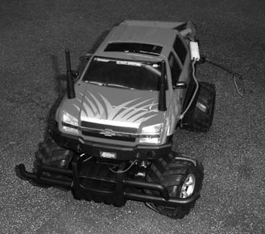
Our remote-control victim car is a Chevy Avalanche, shown in Figure 4-39, that I picked up for about $10 at the local Radio Shack. Its retail price is about $30; this one was cheap because it was a display model with no remote. Since the whole point of this hack is to replace the remote with Wi-Fi, it was an even better deal!
The router’s GPIO pins can source only a few milliamps, but the drive motors of the car want up to two Amperes (amps) at stall. To convert between the low-power outputs of the router and the high-power needs of the car, Bell Laboratories invented the transistor in 1947 to do exactly that.
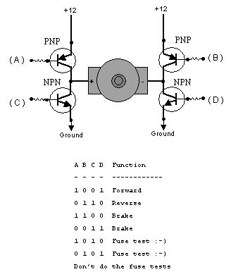
However, a transistor can provide only high-voltage (known as logic high) or low-voltage (known as logic low), but not both. The motors will need one side high and one side low to drive forward, and the reverse of that to drive backwards. So, each side of the motor must have a high-side transistor (known as PNP), and a low side transistor (known as NPN). When connected together, the schematic looks something like the letter H with a transistor on each leg and the motor in the middle, as shown in Figure 4-40.
It is possible to build this schematic from scratch, using eight transistors to drive two motors. However, this is unnecessarily complicated in the Integrated Circuit age. For a few bucks, you can get all this in a neat little package. I used the SN754410, available from Acroname for five dollars at http://www.acroname.com/robotics/parts/R6-754410.html. Fortunately, I ordered three.
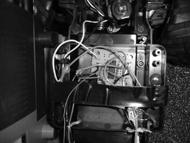
Using a small proto-board and five-volt regulator model 7805 (http://tinyurl.com/wqbv) from Radio Shack, I put together a small driver board. It had 10 wires coming out of it: two power wires connected directly to the drive battery, and four small wires connected to a telephone connector that plugged into the router (so the router wasn’t soldered to the car).
The drive motors, however, were soldered directly to the board, providing the last four wires that came into the board. The first time I powered it up, I was sure to test all the connections, because I felt something bad would happen. It did; I made sure that the power wires were indeed the power wires, but I forgot to check the polarity! The chip went up in smoke, leaving charred remains. Undaunted, I rebuilt the circuit with one of the other chips that I ordered and, finally, the driver board worked. Figure 4-41 shows the finished driver board installed inside the Chevy.
I taped the router to the bare base of the car to test it out; it worked! It looked ugly, but after connecting to the car’s access point, using an SSH client to start the RC car server program rcServ, and loading my VB client, the car moved! I could have finished there, but I decided to see if it could work with the Chevy Avalanche cover on, just for looks.
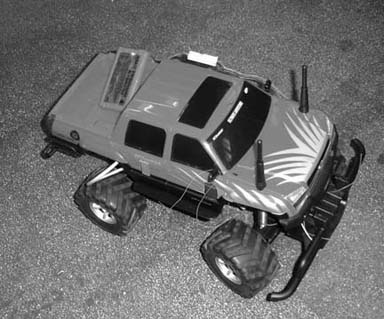
A friend of mine, Manny, decided to take it upon himself to do this part. Using a dremel, he cut holes in the side of the case for the legs of the router, and also two holes up front for the antennas. Although I calculated that the car would work up to a hundred feet without the antennas, he decided to put the holes in, anyway. Given that it was his first time using the tool, results were as expected: the case still has to be stretched to fit the router, and even so it scratches the sides, as well as the antennas.
Needless to say, the blue and black protrusions in the side of the red car are also an eyesore. Although it is better than without the cover, I would have chosen a better way to fit the router inside the case. Hey, if you want something done right, you have to do it yourself. But, as shown in Figure 4-42, it does look cool!
Here’s the final result: the WiFiCar. It’s far from perfect, but it does provide a base from which to expand; many people have contacted me about adding cameras, GPS, autonomy, and various other additions to the car. I’m also working on a bigger version using a 1/6th scale Hummer. But this is, to my knowledge, the first self-controlled wireless router.
Tip
For more details on the car, including a video of it actually moving under Wi-Fi control, check out the project web site at http://yasha.okshtein.net/wrt54g.
—Yasha Okshtein
Get Wireless Hacks, 2nd Edition now with the O’Reilly learning platform.
O’Reilly members experience books, live events, courses curated by job role, and more from O’Reilly and nearly 200 top publishers.

