Power your access point without running a separate power cable by using free pairs on the CAT5.
A number of access point manufacturers (Lucent, Symbol, and D-Link, to name three) are now offering Power over Ethernet (PoE) add-ons for their access points. A PoE module inserts DC voltage into the unused wires in a standard Ethernet cable (pairs 7-8 and 4-5). The idea is to supply the AP’s power and UTP Ethernet connectivity requirements via a single Ethernet cable. This works great in areas where you may not have power easily accessible, such as a roof. This also allows you to more easily place the AP closer to the antenna, thus reducing signal loss over antenna cabling. Ethernet signal travels well over CAT5 cable; a 2.4 GHz signal doesn’t do as well over antenna cabling. Also, Ethernet cabling is much cheaper than antenna cable such as LMR400. The following hack demonstrates how to build a simple PoE module pair.
Warning
Don’t try this unless you have some knowledge of electricity. 12v isn’t going to kill you, but you may cause serious damage to your access point and other equipment. Don’t blame me if something goes wrong. I’m not an electrical engineering major, I’m just a networking guy who wanted cheap PoE modules, and decided to write about how I did it.
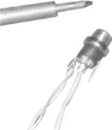
Solder wires to the DC Male Power Plug. Solder one pair (two wires twisted together) to the inner-contact connection. These will be the positive power wires. Solder another pair to the outer-contact connection. Notice that on this DC Male Power Plug, there are three connectors. One is for the center pin, one is for the outer surface, and one goes to the plug-housing. You do not need to solder anything to the plug-housing connector. Figure 4-30 shows what it should look like when finished.
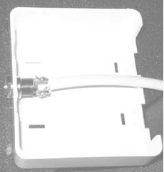
Drill a hole in your two-port mount housing. Mount the Male DC plug in the housing, as shown in Figure 4-31.
Connect the wires in your two-port jack as follows (note that this is the Intel Symbol, Orinoco Standard, not the Cisco standard for wiring):
|
Input jack |
Output jack |
DC plug | ||
|---|---|---|---|---|
|
Pin 1 |
<-> |
Pin 1 | ||
|
Pin 2 |
<-> |
Pin 2 | ||
|
Pin 3 |
<-> |
Pin 3 | ||
|
Pin 4 |
<-> |
DC Positive Wire 1 → Center Connector | ||
|
Pin 5 |
<-> |
DC Positive Wire 2 → Center Connector | ||
|
Pin 6 |
<-> |
Pin 6 | ||
|
Pin 7 |
<-> |
DC Negative Wire 1 → Outer Connector | ||
|
Pin 8 |
<-> |
DC Negative Wire 2 → Outer Connector |
Wire the one port wall mount jack as follows:
|
Output plug |
Input jack |
DC plug | ||
|---|---|---|---|---|
|
Pin 1 |
<-> |
Pin 1 | ||
|
Pin 2 |
<-> |
Pin 2 | ||
|
Pin 3 |
<-> |
Pin 3 | ||
|
Pin 4 |
<-> |
DC Positive Wire 1 → Center Connector | ||
|
Pin 5 |
<-> |
DC Positive Wire 2 → Center Connector | ||
|
Pin 6 |
<-> |
Pin 6 | ||
|
Pin 7 |
<-> |
DC Negative Wire 1 → Outer Connector | ||
|
Pin 8 |
<-> |
DC Negative Wire 2 → Outer Connector |
Plug in and test. The completed modules are shown in Figure 4-32.

The DC resistance of Cat5 is about 3 ohms per 100 feet per conductor, so a 250-foot cable has at least 7 ohms resistance. Most of the time, the APs draw much less than 0.8A, so you would still be above 6V at the AP. In fact, the access points typically use linear regulators to drop the voltage down to 5V on their insides, so as long as you’re giving them something better than 6V at the terminals, they’re likely to work.
There is a good calculator online at http://www.gweep.net/~sfoskett/tech/poecalc.html that calculates the voltage drop for a given length of CAT5. Use it to estimate how much power you need to provide at one end of your cable run in order to power your access point.
—Terry Schmidt
Get Wireless Hacks now with the O’Reilly learning platform.
O’Reilly members experience books, live events, courses curated by job role, and more from O’Reilly and nearly 200 top publishers.

