Alternative Base Switching
28 In the examples of transistor switching, the actual switching was performed using a small mechanical switch placed in the base circuit of the first transistor. This switch has three terminals and switches from position A to position B. (This is a single-pole, double-throw switch.) This switch does not have a definite ON or OFF position, as does a simple ON-OFF switch.
Question
Why couldn't a simple ON-OFF switch with only two terminals have been used with these examples? _____
An ON-OFF switch is either open or closed, and cannot switch between position A and position B, as shown earlier in Figure 4.19.
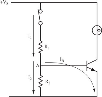
29 If you connect R1, R2, and a switch together, as shown in Figure 4.20, you can use a simple ON-OFF switch with only two terminals. (This is a single-pole, single-throw switch.)
30 When the switch is closed, current flows through R1. However, at point A in Figure 4.20, the current divides into two paths. One path is the base current IB, and the other is marked I2.
Question
How could you calculate the total current I1? _____
31 The problem now is to choose ...
Get Complete Electronics Self-Teaching Guide with Projects now with the O’Reilly learning platform.
O’Reilly members experience books, live events, courses curated by job role, and more from O’Reilly and nearly 200 top publishers.


