A walkthrough of configuration examples, starting with basic examples and then getting into a few more complex configurations, will help to put this into perspective. The order of the walkthrough uses the following configuration examples:
Gigabit Ethernet interfaces
Gigabit Ethernet with VLAN tagging
T1 interface with Cisco HDLC
Serial interface with PPP
Serial interface with Frame Relay
DSL
MLPPP
Aggregated Ethernet interfaces
GRE Tunnel Interfaces
Initially, we will use a step-by-step approach to establish the configuration fundamentals. Then the walkthrough will move toward configuration results that build on the fundamentals and become advanced. Once you grasp the fundamentals, you should be able to follow the advanced configurations. At the end of this section, we will discuss the use of the Virtual Router Redundancy Protocol (VRRP).
First, let’s build an interface on router Lager that connects directly to router
Ale over the ge-0/0/0 interface.
Check the status of the ge-0/0/0 interface by issuing a show interfaces ge-0/0/0
terse command. Junos interfaces are automatically “enabled”
when the physical connection is wired:
root@Lager> show interfaces terse ge-0/0/0
Interface               Admin Link Proto    Local            Remote
ge-0/0/0                up    up
Note
If an interface needs to be administratively disabled, issue the
set interfaces
<interface name> disable command.
The interface appears to be physically up, so next, configure the interface to allow IP traffic to flow as well as add an IP address. Begin by entering configuration mode, dropping down to the hierarchy of the interface, and configuring the correct family and local IP address:
root@Lager>configureEntering configuration mode [edit] root@Lager#edit interfaces ge-0/0/0[edit interfaces ge-0/0/0] root@Lager#set unit 0 family inet address 10.10.20.122/24
Since this is a non-VLAN-tagged Ethernet interface, unit 0 must be used when configuring the logical properties of family inet.
Also, note that Junos requires a mask for every IP address in the classless interdomain routing (CIDR) “slash” notation. An absence of the mask can lead to the less desirable result of configuring a /32 subnet on your interface. (Look for other Junos address issues in Interface Troubleshooting.)
Verify the configuration and activate the changes by issuing
a commit and-quit
command:
[edit interfaces ge-0/0/0] root@Lager#showunit 0 { family inet { address 10.10.20.122/24; } } [edit interfaces ge-0/0/0] root@Lager#commit and-quitcommit complete Exiting configuration mode
Verify the status of the interface. Note that the status now includes the logical portion as well as the physical portion of the interface:
root@Lager> show interfaces terse ge-0/0/0
Interface               Admin Link Proto    Local              Remote
ge-0/0/0                up    up
ge-0/0/0.0              up    up   inet     10.10.20.122/24
Lastly, test connectivity by issuing a ping command toward
the other end of the link of Ale:
root@Lager> ping 10.10.20.121
PING 10.10.20.121 (10.10.20.121): 56 data bytes
64 bytes from 10.10.20.121: icmp_seq=0 ttl=64 time=7.758 ms
64 bytes from 10.10.20.121: icmp_seq=1 ttl=64 time=10.394 ms
^C
--- 10.10.20.121 ping statistics ---
2 packets transmitted, 2 packets received, 0% packet loss
round-trip min/avg/max/stddev = 7.758/9.076/10.394/1.318 ms
Note
Notice the Ctrl-C sequence used to break out of the ping command. Junos will send an endless
number of pings unless a break is issued or a specific number of ping
packets are specified with the count command.
root@Lager> ping 10.10.20.121 count 3

PING 10.10.20.121 (10.10.20.121): 56 data bytes

64 bytes from 10.10.20.121: icmp_seq=0 ttl=64 time=16.822 ms

64 bytes from 10.10.20.121: icmp_seq=1 ttl=64 time=20.382 ms

64 bytes from 10.10.20.121: icmp_seq=2 ttl=64 time=10.370 ms


--- 10.10.20.121 ping statistics ---

3 packets transmitted, 3 packets received, 0% packet loss

round-trip min/avg/max/stddev = 10.370/15.858/20.382/4.144 msContinuing with our example, let’s add VLAN tagging between Lager and Ale, which is already configured with a VLAN
ID of 100. The first step is to enable VLAN tagging on the physical
interface of Lager:
root@Lager>configureEntering configuration mode [edit] root@Lager#edit interfaces ge-0/0/0[edit interfaces ge-0/0/0] root@Lager#set vlan-tagging
Next, add a VLAN ID of 100 on logical unit 0:
[edit interfaces ge-0/0/0] root@Lager#set unit 0 vlan-id 100[edit interfaces ge-0/0/0] root@Lager#showvlan-tagging; unit 0 { vlan-id 100; family inet { address 10.10.20.122/24; } }
Note
Juniper routers do not have a default VLAN, as every VLAN must
be explicitly configured. Many switches use a default VLAN of 1, so
make sure you explicitly configure a vlan-id of 1 on the router for connectivity.
Although this is a valid configuration on unit 0, the best
practice is to always keep the same unit number as the VLAN tag, so
let’s change the unit number with the rename command:
[edit interfaces ge-0/0/0] root@Lager#rename unit 0 to unit 100[edit interfaces ge-0/0/0] root@Lager#showvlan-tagging; unit 100 { vlan-id 100; family inet { address 10.10.20.122/24; } }
Lastly, activate the changes, verify the interface status, and test connectivity:
[edit interfaces ge-0/0/0] root@Lager#top[edit] root@Lager#commitcommit complete [edit] root@Lager#run show interfaces terse ge-0/0/0Interface Admin Link Proto Local Remote ge-0/0/0 up up ge-0/0/0.100 up up inet 10.10.20.122/24 [edit] root@Lager#run ping 10.10.20.121 count 1PING 10.10.20.121 (10.10.20.121): 56 data bytes 64 bytes from 10.10.20.121: icmp_seq=0 ttl=64 time=46.668 ms --- 10.10.20.121 ping statistics --- 1 packets transmitted, 1 packets received, 0% packet loss round-trip min/avg/max/stddev = 46.668/46.668/46.668/0.000 ms [edit] root@Lager#run show interfaces terse ge-0/0/0Interface Admin Link Proto Local Remote ge-0/0/0 up up
Note
Notice the use of the command run to issue the operational mode command
ping in configuration mode.
Also notice the use of the top command prior to the commit command. In some cases a commit can
be issued only from the top. Using top will save time otherwise spent issuing
multiple commit commands.
The T1 interface is the most popular basic physical layer protocol used by the Digital Signal level 1 (DS1) multiplexing method in North America. For point-to-point interfaces on Juniper Networks routers, the default Layer 2 encapsulation is PPP, which differs from many other vendors’ default behavior. To quickly interoperate with those vendors, change the encapsulation to the default setting, which is usually Cisco HDLC. Since we already showed the step-by-step configuration in the previous configuration, we show here only the result of adding the correct encapsulation:
t1-2/0/2 {
    encapsulation cisco-hdlc;
    unit 0 {
        family inet {
            address 10.200.8.9/30;
        }
    }
}
Note
An inquiring mind may wonder why the encapsulation has the word cisco in it. Is there a non-Cisco HDLC? As a matter of fact, there is! There is a standard HDLC protocol (ISO 13239), used in protocols such as X.25 and SDLC. The original specification did not have multiprotocol support, so Cisco decided to create its own version with this support with different header fields and definitions. Although this protocol is officially proprietary, the workings are open and have been implemented by many different router vendors.
A serial interface can come in a variety of different physical forms, such as V.35, X.21, and EIA-530. The choice of physical media often depends on geographical location; V.35 is the most common choice in the United States and Europe, and X.21 is more common in Japan. Regardless of physical media, all serial interfaces have the same idea of defining a data circuit-terminating equipment (DCE) device and a data terminal equipment (DTE) device. The DTE device is the end unit that receives data encoding, clocking, and signal conversion from the DCE device. In modern communications, the DCE device often takes the form of a channel service unit/data service unit (CSU/DSU) or a modem; however, when connecting two routers in a back-to-back fashion, one of the routers takes the role of a DCE.
Router Ale and router Bock have a back-to-back serial connection
using V.35 with the default encapsulation of PPP. Normally, a router
will default to DTE mode, but in this case, Ale is automatically chosen as the DCE based
on the detection of a DCE cable. You can observe this detection in the
Local mode field of the show interfaces
command:
root@ale# run show interfaces se-1/0/0 extensive | find "serial media"
  Serial media information:
    Line protocol: v.35
    Resync history:
      Sync loss count: 0
    Data signal:
      Rx Clock: Not Detected
    Control signals:
      Local mode: DCE
      To DTE: CTS: up, DCD: up, DSR: up
      From DTE: DTR: up, RTS: up
    DCE loopback override: Off
    Clocking mode: loop-timed
    Loopback: none
    Tx clock: non-invert
    Line encoding: nrz
Since one of the roles of the DCE is to provide clocking to the
DTE, an internal clocking mode needs to be configured on Ale. This allows Ale to generate a clocking signal toward
Bock using the internal clock with a
default clock rate of 8 MHz:
[edit interfaces]
root@ale# show se-1/0/0
serial-options {
    clocking-mode internal;
}
unit 0 {
    family inet {
        address 172.16.1.1/30;
    }
}
Bock has no clocking mode
configured and takes the default clock mode of loop-timed, which takes
the transmitted clock from Ale.
Bock could also have been configured for DCE mode,
which would have the same result in this case. Here is the Bock configuration:
[edit interfaces se-1/0/1]
root@Bock# show
unit 0 {
    family inet {
        address 172.16.1.2/30;
    }
}
You can verify the local mode, clocking mode, and clock rate on
Bock by using the show interfaces
command:
[edit interfaces se-1/0/1]
root@Bock# run show interfaces se-1/0/1 extensive | find "serial media"
  Serial media information:
    Line protocol: v.35
    Resync history:
      Sync loss count: 0
    Data signal:
      Rx Clock: OK
    Control signals:
      Local mode: DTE
      To DCE: DTR: up, RTS: up
      From DCE: CTS: up, DCD: up, DSR: up
    Clocking mode: loop-timed    Clock rate: 8.0 MHz
    Loopback: none
    Tx clock: non-invert
    Line encoding: nrz
Note
Clocking can often be a confusing topic for many users. For back-to-back router connections, Juniper made it simple by allowing multiple different clocking modes to be configured and still “do the right thing.” The only combinations that will not work for back-to-back connections are the DCE in loop mode and the DTE in loop or DCE mode. However, when connecting to a CSU/DSU or a modem, proper care must be taken to configure the correct clock mode.
Frame Relay is a Layer 2 encapsulation that enables the connection of your LAN via a WAN connection to a Frame Relay node. Frame Relay creates a tunnel called a permanent virtual circuit (PVC) over a private or leased line to provide connectivity to other sites over the Internet service provider’s (ISP’s) infrastructure. With the emergence of DSL and IP-based networks, Frame Relay is not often seen anymore, except in rural areas as a cheaper, “always on” connection.
To establish a Frame Relay connection with the Frame Relay node,
the proper encapsulation of frame-relay (RFC 1490) must be configured as well as the local circuit
identifier for the PVC represented by the logical property of a dlci number:
se-1/0/0 {
    encapsulation frame-relay;
    unit 645 {
        description "to R3";
        dlci 645;
        family inet {
            address 172.17.24.130/30;
        }
    }
}
The router can also support back-to-back router connections by configuring one router to operate in DCE mode or by turning off keepalives on each router. If keepalives are disabled, the router will not wait for any local management messages to enable that interface. Also, turning keepalives off can help in troubleshooting by allowing for loopback testing, which we’ll discuss later in this chapter.
DSL is one of the more popular connection media for both companies and consumers because the local service is provided via a normal phone line with a DSL modem. This connection terminates at the telco digital subscriber line access multiplexer (DSLAM), a device that concentrates multiple DSL connections together. Some J-series routers have support for ATM over asymmetrical digital subscriber line (ADSL)—Annex A for DSL over POTS or Annex B for DSL over ISDN—and symmetric high-speed digital subscriber line (SHDSL) configurations that allow them to act as the DSL modem at the customer site. The interfaces appear to be ATM connections but do not support native ATM, only the use of ATM over a DSL connection.
Router PBR has an ADSL Annex A
PIM installed in slot 6 and will act as a client to the DSLAM. This
connection is using Point-to-Point Protocol over Ethernet
(PPPoE) over ATM for the DSL connection, which requires that two
different interfaces be configured. The first interface that is
configured is the physical ATM interface of at-6/0/0. To configure the interface, the ATM
virtual path and virtual channel identities must be the same values that
are provisioned at the DSLAM. The rest of the parameters can be learned
from the DSLAM by setting an operating mode of auto. Since PBR will be using PPPoE, the encapsulation
must be configured at both the
physical and the logical layers:
 [edit]
doug@PBR# show interfaces
at-6/0/0 {
    encapsulation ethernet-over-atm;
    atm-options {
        vpi 0;
    }
    dsl-options {
        operating-mode auto;
    }
    unit 0 {
        encapsulation ppp-over-ether-over-atm-llc;
        vci 0.39;
    }
}
The next interface that must be configured is the PPPoE internal
router interface. This interface maps the physical interface where PPPoE
will be running, sets the access server’s name and underlying service to
be requested, and sets an IP address. The IP address can be learned automatically
from the access server by specifying the negotiate-address command, as seen in the configuration of PBR that follows, or by setting the IP address
to be static:
pp0 {
    unit 0 {
        pppoe-options {
            underlying-interface at-6/0/0.0;
            access-concentrator mgmgrand;
            service-name "pppserv@mgmgrand";
            auto-reconnect 5;
        }
        family inet {
            negotiate-address
            }
        }
    }
}
You can verify the correct operation of the PPPoE negotiation by
issuing the show pppoe interfaces command:
[edit]
doug@PBR# run show pppoe interfaces
pp0.0 Index 68
  State: Session up, Session ID: 4,
  Service name: pppserv@mgmgrand, Configured AC name: mgmgrand,
  Session AC name: mgmgrand, AC MAC address: 00:05:85:ca:7a:a8,
  Session uptime: 00:22:43 ago,
  Auto-reconnect timeout: 5 seconds, Idle timeout: Never,
Underlying interface: at-6/0/0.0 Index 66To incrementally increase the speed of individual PPP links without adding speed to the physical interfaces, the Multilink Point-to-Point Protocol (MLPPP) was created under RFC 1990. This is essentially a “software” bond of multiple physical PPP interfaces to form one larger logical link, called a bundle. Junos allows for up to eight physical interfaces to be assigned to a bundle.
To support MLPPP on any Juniper Networks router, the router must support this special service. This support could be in the form of an additional hardware PIC on an M-series router, or it could inherit software support on other Juniper routers.
The first step is to configure the pseudolink service interface,
which takes the form of lsq-0/0/0 on
J-series, MX, and SRX routers, or an ml, lsq, or
ls interface on an M-series router, depending on the PIC
type. This interface will take all the same characteristics of a normal
PPP interface, such as an IP address, but will have a logical
encapsulation of multilink-ppp. This
is configured at the logical layer of the interface to allow multiple
bundles and types of bundles on the same router by configuring multiple
unit numbers. As shown here, the bundle is assigned to logical unit
0:
lsq-0/0/0 {
    unit 0 {
        encapsulation multilink-ppp;
        family inet {
            address 172.8.17.30/30;
        }
    }
}
Next, configure the physical interfaces to link the newly created
link service interface. In the following example, interfaces se-1/0/0 and se-1/0/1 are linked to the logical bundle unit
0 on the ls-0/0/0 interface:
se-1/0/0 {
    unit 0 {
        family mlppp {
            bundle lsq-0/0/0.0;
        }
    }
}
se-1/0/1 {
    unit 0 {
        family mlppp {
            bundle lsq-0/0/0.0;
        }
    }
}
To verify the status, issue the show interfaces terse
command. Notice that both the serial interfaces and the link service
interfaces are tracked. The link service will be in the up state as long
as one of the physical interfaces is also in the up state. You can
modify this by configuring the minimum-links number
command under the link service interface. This command sets the number
of physical links that must be in the up state for the bundle to be
labeled up:
root@Bock# run show interfaces terse | match "se|lsq-"
lsq-0/0/0                up    up
lsq-0/0/0.0              up    up   inet     172.17.8.30/30
se-1/0/0                 up    up
se-1/0/0.0               up    up   mlppp    lsq-0/0/0.0
se-1/0/1                 up    up
se-1/0/1.0               up    up   mlppp    lsq-0/0/0.0
Note
Notice the use of an “or” statement in the match criteria. The
use of quotes and the pipe symbol denotes an or statement for the
match, looking for lines that contain either se or lsq-.
The IEEE 802.3ad standard defines a means to bundle multiple Ethernet interfaces into an aggregate group. Traffic is passed over all members of the group in a load-balancing arrangement. The link aggregation control protocol (LACP) can be added to monitor the bundle, allowing interfaces to be added or subtracted from the bundle without loss of traffic.
The use of 802.3ad allows multiple connections between a router and a switch without the possibility of a broadcast storm. This improves performance and has a quicker recovery time than using a spanning tree protocol.
The configuration of 802.3ad has three parts: setting the chassis parameters, the aggregate interface, and the participating interfaces. The chassis parameters define the total number of aggregate interfaces that will be set on the router. In this example, we are installing only a single aggregate interface:
root@Lager> show configuration chassis
aggregated-devices {
    ethernet {
        device-count 1;
    }
}
The aggregate interface uses an internal interface type of ae0. This interface carries the logical interface properties for the interface—in this case, the IP address for the bundle:
root@Lager> show configuration interfaces ae0
unit 0 {
    family inet {
        address 4.4.4.1/24;
    }
}
Finally the participating interfaces are added to the configuration. Up to 10 Ethernet interfaces can be added to an aggregate bundle. These interfaces can be in any location on the router:
root@Lager>show configuration interfaces ge-0/0/2gigether-options { 802.3ad ae0; } root@Lager>show configuration interfaces ge-0/0/3gigether-options { 802.3ad ae0; }
Once the configuration is entered and committed, the ae0 interface
is monitored as any other interface on the router. The show interfaces ae0
command shows the interface’s bandwidth and status. The show interface terse command shows the addresses of the aggregate interface and the
bundle of the aggregated Ethernet interfaces:
root@Lager>show interfaces ae0Physical interface: ae0, Enabled, Physical link is Up Interface index: 146, SNMP ifIndex: 142 Link-level type: Ethernet, MTU: 1514, Speed:2000mbps, BPDU Error: None, MAC-REWRITE Error: None, Loopback: Disabled, Source filtering: Disabled, Flow control: Disabled, Minimum links needed: 1, Minimum bandwidth needed: 0 Device flags : Present Running Interface flags: SNMP-Traps Internal: 0x4000 root@Lager>show interfaces terse | match "ge-|ae0".... ge-0/0/2 up up ge-0/0/2.0 up up aenet --> ae0.0 ge-0/0/3 up up ge-0/0/3.0 up up aenet --> ae0.0 ae0 up up ae0.0 up up inet 4.4.4.1/24
Generic Routing Encapsulation (GRE) is a tunneling protocol that enables the transport of a variety of Layer 3 protocols. The tunnel created by GRE was designed to be “stateless” with no monitoring of the tunnel endpoint. GRE tunnels are used for a variety of applications, including providing backup links, transporting non-IP protocols over an IP network, and connecting “islands” of IP networks.
To create a GRE tunnel on a Juniper Networks router, the router
must be equipped with Layer 2 service capabilities, which are native in
the J-series, MX, and SRX routers and are available via a hardware PIC
in an M-series router. When these services are enabled on a router, a
pseudointerface called gr is created.
The interface must be configured with the source IP address for the GRE
packets, the destination of the tunnel, and the families of protocols
that will be carried in the protocol. The GRE tunnel configured in the
following case is carrying IP traffic and is using a source IP address
of 10.20.1.38 and a destination of 172.66.13.1. An IP address for the
gr-0/0/0 interface is not required
but could be useful for management purposes:
gr-0/0/0 {
    unit 0 {
        tunnel {
            source 10.20.1.38;
            destination 172.66.13.1;
        }
        family inet
    }
}
Note
It is important not to mistake the internal gre interface with the gr interface on the router. The gre interface is used by the router
internally and should not be configured to create GRE tunnels.
The final piece is mapping actual traffic for use by the GRE
tunnel. This is accomplished in a variety of methods depending on the
type of traffic entering the GRE tunnel. Common mapping examples for IP
include creating a static route with a next-up of the gr interface or even running a routing
protocol such as Open Shortest Path First (OSPF) over the interface!
Anybody using a PC for Internet surfing, music downloads, or gaming uses IP as the network protocol. The PC will have an IP address assigned as well as a default gateway address to reach any destinations that are not on the local subnet. In the following code snippet, a PC is using an IP address of 10.70.129.36 with a mask of 255.255.255.0 and a default gateway of 10.70.129.1:
Microsoft Windows [Version 6.0.6002]
Copyright <c> 2006 Microsoft Corporation

C:\Documents and Settings\Douglas Marschke>ipconfig

Ethernet adapter Local Area Connection 3:

        Connection-specific DNS Suffix  . : eu-af.regus.local
        IP Address. . . . . . . . . . . . : 10.70.129.36
        Subnet Mask . . . . . . . . . . . : 255.255.255.0
        Default Gateway . . . . . . . . . : 10.70.129.1
This default gateway address is either statically defined by the user or learned via the Dynamic Host Configuration Protocol (DHCP) process. Regardless of the method, the default gateway will be used as the next hop address for the default route that will be created to reach remote destinations:
Microsoft Windows [Version 6.0.6002]
Copyright <c> 2006 Microsoft Corporation
C:\Documents and Settings\Douglas Marschke>netstat -r
Route Table
================================================================
Interface List
0x1 ......................... MS TCP Loopback interface
0x2 ...00 12 f0 ac 46 d5 ..... Intel(R) PRO/Wireless 2200BG Network
Connection - Packet Scheduler Miniport
0x3 ...00 12 3f 12 d7 59 ...... Broadcom NetXtreme 57xx Gigabit
Controller - Packet Scheduler Miniport
0x20005 ...00 ff e8 25 91 85 ..... Juniper Network Connect Virtual
Adapter
================================================================
Active Routes:
Network Destination Netmask Gateway Interface Metric
0.0.0.0 0.0.0.0 10.70.129.1 10.70.129.36 20
10.70.129.0 255.255.255.0 10.70.129.36 10.70.129.36 20
10.70.129.36 255.255.255.255 127.0.0.1 127.0.0.1 20
10.255.255.255 255.255.255.255 10.70.129.36 10.70.129.36 20
127.0.0.0 255.0.0.0 127.0.0.1 127.0.0.1 1
224.0.0.0 240.0.0.0 10.70.129.36 10.70.129.36 20
255.255.255.255 255.255.255.255 10.70.129.36 10.70.129.36 1
255.255.255.255 255.255.255.255 10.70.129.36 2 1
255.255.255.255 255.255.255.255 10.70.129.36 20005 1
Default Gateway: 10.70.129.1
==============================================================
Persistent Routes:
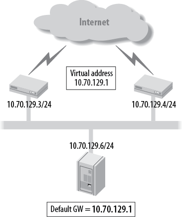
NoneIf the default gateway was a single device and that device failed, a PC would not be able to reach destinations outside the local subnet. In a fault-tolerant network, it would be ideal to have a backup gateway device, without having to modify the configuration on the PC, as well as being able to load-share with multiple PCs on the LAN.
VRRP was created to eliminate single points of behavior that are inherent to static default routed networks. VRRP creates a logical grouping of multiple physical routers to a “virtual” router that will be used as the default gateway for end hosts. This allows the PC to always maintain the same gateway address even if the physical gateway has changed (see Figure 4-16). The routers that are part of the same VRRP logical group will share this “virtual” IP address as well as a “virtual” media access control (MAC) address. Essentially VRRP describes an election protocol to maintain ownership of this virtual IP (VIP) address and MAC address. One router in the VRRP group will be the master router, which controls this VIP address unless a failure occurs that results in a release of that ownership. This failure causes another router to claim ownership of the VIP by issuing a VRRP message and a gratuitous Address Resolution Protocol (ARP) to claim the virtual MAC address. Once a router becomes the master, it will periodically advertise VRRP messages to indicate its overall health and reachability.
When configuring VRRP for the first time on a Juniper Networks router, it can seem like locating the configuration is similar to trying to find a needle in a haystack. The configuration will be within the logical property and will be configured after the family inet address. A VRRP group value (1–255) is assigned on every router that needs to be part of the virtual router. Also, a VIP address is assigned that the hosts will use as their gateway address. This could be an address owned by one of the routers in the group or an address taken out of the address block owned by the LAN. Lastly, a priority value can be configured to change the default value of 100, which is used to elect the master router of the VRRP group. The router with the highest priority value becomes the master for that group; if the priorities are equal, the tiebreaker goes to the highest local LAN IP address:
lab@LAGER# show interfaces
ge-0/0/1 {
    vlan-tagging;
    speed 100m;
    link-mode full-duplex;
    unit 1115 {
        description LAGER-to-ALE;
        vlan-id 1115;
        family inet {
            address 10.40.1.2/24 {
                vrrp-group 1 {
                    virtual-address 10.40.1.200;
                    priority 200;

                }
            }
        }
    }
Verify the operation of VRRP with the show vrrp summary
command. Router Lager is the master
for group 1 because it has a higher priority:
[edit interfaces ge-0/0/1]
lab@LAGER# run show vrrp summary
Interface     State       Group   VR state       VR Mode    Type   Address
ge-0/0/1.0    up              1   master          Active    lcl    4.4.4.1
                                                            vip    4.4.4.100
Note
Priority values range from 0–255; however, only values 1–254 are configurable. Priority 0 is reserved for the master router to issue an immediate release of mastership. A priority of 255 is used if the VIP is an actual interface IP that is owned by that router.
Another option that can be configured is the ability to track the
interface priority settings. If an interface goes down, the advertised
priority will be subtracted by a configured value. This could result in
a new master router for the virtual router. This is very useful to
ensure upstream reachability. In the example on Lager, a T1 interface is being tracked. If
this interface goes down, 150 will be subtracted from the configured
priority of 200:
lab@LAGER# show interfaces
ge-0/0/1 {
    vlan-tagging;
    unit 1115 {
        description LAGER-to-ALE;
        vlan-id 1115;
        family inet {
            address 10.40.1.2/24 {
                vrrp-group 1 {
                    virtual-address 10.40.1.200;
                    priority 200;

                    track {
                        interface t1-2/0/2.0 priority-cost 150;
                    }
                }
            }
        }
    }
You can force an interface failure by administratively disabling the T1 interface:
lab@LAGER# top set interfaces t1-2/0/2 disable

[edit]
lab@LAGER# commit
commit complete
The result of this failure is a mastership change, as Lager is now the backup router:
[edit] lab@LAGER#run show vrrp summaryInterface State Group VR state VR Mode Type Address ge-0/0/1.0 up 1backupActive lcl 4.4.4.1 vip 4.4.4.100
Notice in the show vrrp track
command that Lager has a configured
(cfg) priority value of 200, but a
priority of 50 is currently being used because we’ve subtracted the cost
of 150 from the downed T1 interface:
lab@LAGER# run show vrrp track
Track Int   State         Speed   VRRP Int   Group   VR State      Current prio
t1-2/0/2.0  down              0   ge-0/0/1.0     1   backup                  50
The default behavior of VRRP is to use preemption, which causes a router with a higher priority to become the
master at any time. When Lager’s T1
interface is reenabled, it will again become the master for the virtual
router:
[edit] lab@LAGER#rollback 1load complete [edit] lab@LAGER#commitcommit complete [edit] lab@LAGER#run show vrrp trackTrack Int State Speed VRRP Int Group VR State Current prio se-1/0/0.0 up 16384k ge-0/0/3.0 1master200
Since preemption could cause a temporary disruption in the
network, a no-preempt command can
also be configured.
Lastly, according to RFC 3768, “A VRRP router SHOULD not forward packets addressed to
the VIP Address(es) it becomes Master for if it is not the owner.” That
means if we have an IP address that is not owned by any router and is
simply an address from the subnet that was used as the VIP, operational
issues may appear. The most common issue is not being able to ping the
virtual address. In the case just examined, 10.40.1.200 was the VIP
address chosen out of the 10.40.1/24 subnet, but it was not actually
configured on either Lager or
Ale. Juniper routers allow you to
break this rule by configuring the accept-data command to
allow the master router to respond to the VIP address. This will allow
testing to occur toward the VIP; however, care must be taken to avoid
unnecessary traffic on the LAN.
Get Junos Enterprise Routing, 2nd Edition now with the O’Reilly learning platform.
O’Reilly members experience books, live events, courses curated by job role, and more from O’Reilly and nearly 200 top publishers.

