Interfaces can have a variety of issues depending on the actual interface type, and listing all the possibilities would require a separate book! Instead, in this section, we will discuss a few common issues that illustrate the types of troubleshooting commands available on the router.
Since Juniper Networks routers allow multiple IP addresses to be
configured on a single logical unit, configuration errors can occur if
care is not taken. Lager has an IP
address of 10.10.20.122 configured on its gigabit Ethernet interface
with a subnet mask of /24. This was noticed to be a configuration error,
as the mask should have been configured for /27:
[edit interfaces ge-2/0/1]
root@Lager# show
vlan-tagging;
unit 100 {
    vlan-id 100;
    family inet {
        address 10.10.20.122/24;
    }
}
Here, the address of 10.10.20.122 is added with the correct subnet of /27:
[edit interfaces ge-2/0/1]
root@Lager# set unit 100 family inet address 10.10.20.122/27
When you view the resultant interface configuration, the router appears to contain the duplicate IP addresses with varying subnet masks. This illustrates the fact that IP addresses are not overridden per logical unit, but simply are added to the logical unit:
[edit interfaces ge-2/0/1]
root@Lager# show
vlan-tagging;
unit 100 {
    vlan-id 100;
    family inet {
        address 10.10.20.122/24;
        address 10.10.20.122/27;
    }
}
To correct this, the old address with the /24 mask is removed by
use of the delete command:
[edit interfaces ge-2/0/1]
root@Lager# delete unit 100 family inet address 10.10.20.122/24
Another solution with the same result is to use the rename command to
change the subnet mask from /24 to /27:
[edit interfaces ge-2/0/1 unit 100]

root@Lager# rename address 10.10.20.122/24 to address 10.10.20.122/27
Since Juniper Networks routers allow placement of multiple addresses on a single logical interface, care must also be taken to allow for the router to choose the correct source IP address for outgoing packets on that interface. By default, the source IP address is chosen by using the primary and preferred addresses assigned to the interface. Each unit can have only one primary address, but each interface can have multiple preferred addresses. Simply put, a primary address is the address chosen to source local packets out of the interface destined for a remote network. As shown in the following output, 10.20.20.122 is the only address on the interface, and as such, it contains both a primary and a preferred flag:
root@Lager# run show interfaces ge-2/0/1.100
  Logical interface ge-2/0/1.100 (Index 67) (SNMP ifIndex 45)
   Flags: SNMP-Traps 0x4000 VLAN-Tag [0x8100.100] Encapsulation: ENET2
    Input packets : 2215
    Output packets: 23
    Protocol inet, MTU: 1500
      Flags: None
      Addresses, Flags: Is-Preferred Is-Primary
        Destination: 10.10.20.96/27, Local: 10.10.20.122,
        Broadcast: 10.10.20.127
Now configure two additional IP addresses, 6.6.6.6 and 6.6.6.4, on the interface and observe the results:
root@Lager#set address 6.6.6.4/24root@Lager#set address 6.6.6.6/24[edit interfaces ge-2/0/1 unit 100 family inet] root@Lager#commitcommit complete [edit interfaces ge-2/0/1 unit 100 family inet] root@Lager#run show interfaces ge-2/0/1.100 | find protocolProtocol inet, MTU: 1500 Flags: None Addresses, Flags: Is-Preferred Is-Primary Destination: 6.6.6/24, Local: 6.6.6.4, Broadcast: 6.6.6.255 Addresses Destination: 6.6.6/24, Local: 6.6.6.6, Broadcast: 6.6.6.255 Addresses, Flags: Is-Preferred Destination: 10.10.20.96/27, Local: 10.10.20.122, Broadcast: 10.10.20.127
The primary address has changed to 6.6.6.4, and now two addresses contain the preferred flag: addresses 6.6.6.6 and 10.10.20.122. The preferred address is used as the source IP address if you’re trying to reach a network that is locally attached. In this case, if traffic is destined for 172.16.1.2, the source IP address of 6.6.6.4 is used, but if the destination address is 10.10.20.121, the source IP address of 10.10.20.122 will be used. Junos by default will choose the primary and preferred addresses based on the lowest IP address that is configured. The primary address will be the lower IP address configured on the interface, and the preferred address will be the lowest IP address configured for each local subnet. In the earlier example, traffic destined to a host on the 6.6.6/24 subnet is sourced from 6.6.6.4. You can modify these defaults by configuring the appropriate flag (primary or preferred) to the address of choice:
[edit interfaces ge-2/0/1 unit 100 family inet] root@Lager#set address 10.10.20.122/27 primary[edit interfaces ge-2/0/1 unit 100 family inet] root@Lager#commitcommit complete
The 10.10.20.122 address has now been configured for the primary
address of the interface, as indicated by the show interfaces
command:
[edit interfaces ge-2/0/1 unit 100 family inet] root@Lager#run show interfaces ge-2/0/1.100 | find protocolProtocol inet, MTU: 1500 Flags: None Addresses, Flags: Is-Preferred Destination: 6.6.6/24, Local: 6.6.6.4, Broadcast: 6.6.6.255 Addresses Destination: 6.6.6/24, Local: 6.6.6.6, Broadcast: 6.6.6.255 Addresses, Flags: Primary Is-Preferred Is-Primary Destination: 10.10.20.96/27, Local: 10.10.20.122, Broadcast: 10.10.20.127 [edit interfaces ge-2/0/1 unit 100 family inet] root@Lager#set address 6.6.6.6/24 preferred
For two routers’ interfaces to communicate properly, the same
Layer 2 encapsulation must be configured on each device; depending on
the type of encapsulation, this could be a difficult error to determine.
A common interface medium where this could occur is Ethernet. The
interface on router Lager is
configured to send VLAN tagged frames on the 10.10.20/24 subnet;
however, a ping to router Hangover in
that segment fails:
[edit interfaces ge-2/0/1 unit 100]
root@Lager# run ping 10.10.20.121
PING 10.10.20.121 (10.10.20.121): 56 data bytes
^C
--- 10.10.20.121 ping statistics ---
3 packets transmitted, 0 packets received, 100% packet loss
Looking at the statistics on Lager’s Ethernet interface, a number of Layer
2 channel errors are recorded:
root@Lager#run show interfaces ge-2/0/1 extensivePhysical interface: ge-2/0/1, Enabled, Physical link is Up Interface index: 142, SNMP ifIndex: 37, Generation: 143 Link-level type: Ethernet, MTU: 1514, Link-mode: Full-duplex Speed: 1000mbps, BPDU Error: None, MAC-REWRITE Error: None, Loopback: Disabled,, Source filtering: Disabled, Flow control: Enabled, Auto-negotiation: Enabled, Remote fault: Online Device flags : Present Running Interface flags: SNMP-Traps Internal: 0x4000 Link flags : None CoS queues : 8 supported, 8 maximum usable queues Hold-times : Up 0 ms, Down 0 ms Current address: 00:12:1e:76:1e:29, Hardware address: 00:12:1e:76:1e:29 Last flapped : 2010-04-05 22:01:18 UTC (1w0d 10:11 ago) Statistics last cleared: 2010-04-13 08:10:48 UTC (00:02:18 ago) Traffic statistics: Input bytes : 0 0 bps Output bytes : 230 0 bps Input packets: 0 0 pps Output packets: 5 0 pps Input errors: Errors: 0, Drops: 0, Framing errors: 0, Runts: 0, Policed discards: 0, L3 incompletes: 0,L2 channel errors: 42,L2 mismatch timeouts: ,0 FIFO errors: 0, Resource errors: 0 Output errors: Carrier transitions: 0, Errors: 0, Drops: 0, Collisions: 0, Aged packets: 0, FIFO errors: 0, HS link CRC errors: 0, MTU errors: 0, Resource errors: 0 Egress queues: 8 supported, 8 in use .....
To see whether the Layer 2 channel errors are currently increasing
or whether they are older counters that have not been cleared,
the monitor interface
ge-2/0/1 command is issued. The second column in the following
code snippet shows the interface counter statistics, and the current
delta column indicates real-time statistics recorded since issuing the
monitor command. Layer 2 channel
errors are currently increasing, as the current delta counter
indicates:
Lager                            Seconds: 14         Time: 08:13:54
                                                   Delay: 0/0/50
Interface: ge-2/0/1, Enabled, Link is Up
Encapsulation: Ethernet, Speed: 1000mbps
Traffic statistics:                                   Current delta
  Input bytes:                    0 (0 bps)                     [0]
  Output bytes:                 230 (0 bps)                     [0]
  Input packets:                  0 (0 pps)                     [0]
  Output packets:                 5 (0 pps)                     [0]
Error statistics:
  Input errors:                   0                             [0]
  Input drops:                    0                             [0]
  Input framing errors:           0                             [0]
  Policed discards:               0                             [0]
  L3 incompletes:                 0                             [0]
  L2 channel errors:            105                            [18]
  L2 mismatch timeouts:           0  Carrier transit            [0]
An additional monitor command
is now used to verify that the router is sending out the correct
packets. The monitor traffic
command is the router’s tcpdump[1] utility that allows local router traffic to be observed on
a particular interface. Since Ethernet requires the IP address to MAC
address mapping before sending the FRAME, a series of ARP requests with
an 802.1Q (VLAN) header are sent out to the interface with no response
received. The layer2-header switch is
used to obtain some Ethernet header information as the monitor command is usually Layer 3 and Layer 4
only:
[edit interfaces ge-2/0/1 unit 100]
root@Lager# run monitor traffic interface ge-2/0/1 layer2-headers
verbose output suppressed, use <detail> or <extensive> for full protocol decode
Address resolution is ON. Use <no-resolve> to avoid any reverse lookup delay.
Address resolution timeout is 4s.
Listening on ge-2/0/1, capture size 96 bytes.
....

08:18:09.764757 Out 0:12:1e:76:1e:29 > Broadcast, ethertype 802.1Q (0x8100), length
46: vlan 100, p 0, ethertype ARP, arp who-has 10.10.20.121 tell 10.10.20.122
08:18:10.564781 Out 0:12:1e:76:1e:29 > Broadcast, ethertype 802.1Q (0x8100), length
46: vlan 100, p 0, ethertype ARP, arp who-has 10.10.20.121 tell 10.10.20.122
08:18:12.214889 Out 0:12:1e:76:1e:29 > Broadcast, ethertype 802.1Q (0x8100), length
46: vlan 100, p 0, ethertype ARP, arp who-has 10.10.20.121 tell 10.10.20.122
08:18:12.814634 Out 0:12:1e:76:1e:29 > Broadcast, ethertype 802.1Q (0x8100), length
46: vlan 100, p 0, ethertype ARP, arp who-has 10.10.20.121 tell 10.10.20.122
08:18:13.414648 Out 0:12:1e:76:1e:29 > Broadcast, ethertype 802.1Q (0x8100), length
46: vlan 100, p 0, ethertype ARP, arp who-has 10.10.20.121 tell 10.10.20.122
08:18:14.314858 Out 0:12:1e:76:1e:29 > Broadcast, ethertype 802.1Q (0x8100), length
46: vlan 100, p 0, ethertype ARP, arp who-has 10.10.20.121 tell 10.10.20.122
^C
7 packets received by filter
0 packets dropped by kernel

[edit interfaces ge-2/0/1 unit 100]
root@Lager#
Router Hangover is then
accessed and a ping command toward Lager is issued. The monitor traffic
command is issued at Hangover with
similar output, except for a single important difference. While router
Lager is sending out the ARP packets
with an 802.1Q header (0 × 8100), router Hangover appears to be sending a
non-VLAN-tagged Ethernet frame (0 × 0806), which is the cause of the
Layer 2 channel errors that were previously discovered:
doug@hangover> monitor traffic interface ge-2/0/0 layer2-headers
verbose output suppressed, use <detail> or <extensive> for full protocol decode
Listening on ge-2/0/0, capture size 96 bytes
....
08:20:32.901733 Out 0:12:1e:75:fa:28 > Broadcast, ethertype ARP (0x0806), length 42:
arp who-has 10.10.20.122 tell 10.10.20.121
08:20:33.801530 Out 0:12:1e:75:fa:28 > Broadcast, ethertype ARP (0x0806), length 42:
arp who-has 10.10.20.122 tell 10.10.20.121
08:20:34.601659 Out 0:12:1e:75:fa:28 > Broadcast, ethertype ARP (0x0806), length 42:
arp who-has 10.10.20.122 tell 10.10.20.121
08:20:35.301622 Out 0:12:1e:75:fa:28 > Broadcast, ethertype ARP (0x0806), length 42:
arp who-has 10.10.20.122 tell 10.10.20.121
08:20:36.001475 Out 0:12:1e:75:fa:28 > Broadcast, ethertype ARP (0x0806), length 42:
arp who-has 10.10.20.122 tell 10.10.20.121
08:20:36.941611 Out 0:12:1e:75:fa:28 > Broadcast, ethertype ARP (0x0806), length 42:
arp who-has 10.10.20.122 tell 10.10.20.121
^C
7 packets received by filter
0 packets dropped by kernel
After correcting the configuration error on Hangover to allow for VLAN encapsulation with
the correct VLAN ID, the ping succeeds and is verified:
root@Lager# run monitor traffic interface ge-2/0/1 layer2-headers
verbose output suppressed, use <detail> or <extensive> for full protocol decode
Listening on ge-2/0/1, capture size 96 bytes
...

08:20:55.076174  In 0:12:1e:75:fa:28 > Broadcast, ethertype 802.1Q (0x8100), length
60: vlan 100, p 0, ethertype ARP, arp who-has 10.10.20.122 tell 10.10.20.121
08:20:55.076308 Out 0:12:1e:76:1e:29 > 0:12:1e:75:fa:28, ethertype 802.1Q (0x8100),
length 46: vlan 100, p 0, ethertype ARP, arp reply 10.10.20.122 is-at 0:12:1e:76:1e:
29
08:20:55.096237  In PFE proto 2 (ipv4): 10.10.20.121 > 10.10.20.122: ICMP echo
request seq 0, length 64
08:20:55.096272 Out 0:12:1e:76:1e:29 > 0:12:1e:75:fa:28, ethertype 802.1Q (0x8100),
length 102: vlan 100, p 0, ethertype IPv4, 10.10.20.122 > 10.10.20.121: ICMP echo
reply seq 0, length 64When an IP packet is transiting a network, it is often fragmented so
that it can transverse interfaces with varying sizes of MTUs. However,
some applications do not allow this fragmentation, so you must ensure
that the ingress MTU is not larger than a transit MTU for those
applications. One simple tool you can use to test whether the proper MTU
is assigned is the packet internet
groper (ping) command.
Connectivity to a remote system is confirmed on router Lager by issuing a ping command to an address of
172.17.20.2:
root@Lager> ping 172.17.20.2
PING 172.17.20.2 (172.17.20.2): 56 data bytes
64 bytes from 172.17.20.2: icmp_seq=0 ttl=62 time=7.133 ms
64 bytes from 172.17.20.2: icmp_seq=1 ttl=62 time=10.375 ms
^C
--- 172.17.20.2 ping statistics ---
2 packets transmitted, 2 packets received, 0% packet loss
round-trip min/avg/max/stddev = 7.133/8.754/10.375/1.621 ms
Issue the traceroute command to
check the path these packets take to reach the destination. Router
Lager appears to be located two IP
systems away from the destination of 172.17.20.2:
root@Lager> traceroute 172.17.20.2
traceroute to 172.17.20.2 (172.17.20.2), 30 hops max, 40 byte packets
 1  10.10.20.121 (10.10.20.121)  18.572 ms  12.953 ms  35.782 ms
 2  172.17.20.2 (172.17.20.2)  9.804 ms  9.497 ms  10.003 ms
The application that is being tested requires an MTU of 1,508 bytes, so a ping of size 1,500 is sent with 8 bytes of overhead to the remote station:
root@Lager> ping 172.17.20.2 size 1500 count 3
PING 172.17.20.2 (172.17.20.2): 1500 data bytes
1508 bytes from 172.17.20.2: icmp_seq=0 ttl=63 time=11.591 ms
1508 bytes from 172.17.20.2: icmp_seq=1 ttl=63 time=10.580 ms
1508 bytes from 172.17.20.2: icmp_seq=2 ttl=63 time=20.939 ms

--- 172.17.20.2 ping statistics ---
3 packets transmitted, 3 packets received, 0% packet loss
round-trip min/avg/max/stddev = 10.580/14.370/20.939/4.663 ms
The ping succeeds, and at first glance, all appears well, but
let’s not count our chickens before they hatch! Some examination into
the operation of the ping command is
needed before giving the green light of approval. By default, the ping
packet will be sent out with the do-not-fragment bit cleared in the IP header.
This means that although the ping packet will exit the router with a
size of 1,508 bytes, it could be fragmented along the way. So, now issue
the ping command with the do-not-fragment flag set and observe the
results:
root@Lager> ping 172.17.20.2 size 1500 count 3 do-not-fragment
PING 172.17.20.2 (172.17.20.2): 1200 data bytes
36 bytes from 10.10.20.121: frag needed and DF set (MTU 1119)
Vr HL TOS  Len   ID Flg  off TTL Pro  cks      Src      Dst
 4  5  00 04cc af90   2 0000  40  01 a809 10.10.20.122  172.17.20.2

36 bytes from 10.10.20.121: frag needed and DF set (MTU 1119)
Vr HL TOS  Len   ID Flg  off TTL Pro  cks      Src      Dst
 4  5  00 04cc af91   2 0000  40  01 a808 10.10.20.122  172.17.20.2

^C
--- 172.17.20.2 ping statistics ---
2 packets transmitted, 0 packets received, 100% packet loss
It appears that the intermediate station cannot handle a packet larger than 1,119 bytes on its outgoing interface toward the destination, as observed by the ICMP message that is returned. Luckily, we found this out before the application was deployed, so we were able to correct this problem!
Note
If the outgoing interface on an intermediate system did not contain the proper MTU size, an ICMP error message will be generated. If the incoming interface was configured with a smaller-than-needed MTU, the observation will be different. Since the packet is dropped at input, no ICMP MTU message will be received. Instead, oversize frame errors would increase on the intermediate system’s input interface.
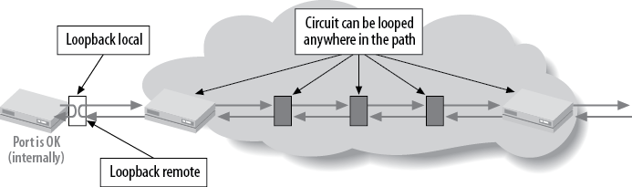
Creating a physical loop on an interface has been a troubleshooting tool for many years. Since the physical path of a leased line frequently consists of multiple segments, often a problem can be localized by testing the circuit segment by segment. The idea is to create a loop at the endpoint of the circuit and send a series of tests toward that endpoint that can determine whether packets are lost or corrupted during transmission. Two types of loops are supported on most types of interfaces: a remote loop and a local loop. A local loop creates a loop toward the router, whereas a remote loop is a line loop that is created toward the downstream network device (see Figure 4-17).
Often, the local LEC will go through a series of tests during the provisioning process to ensure that the circuit integrity includes loopback testing. The circuit may also be left in the looped state to avoid any local alarm generation. To see whether a loop is still in place, issue a ping toward the remote end of the circuit. If the remote end is looped (remote), the ping packets will continue until the Time to Live (TTL) expires, resulting in ICMP TTL expiration messages:
[edit]
doug@PBR# run ping 10.200.8.10
PING 10.200.8.10 (10.200.8.10): 56 data bytes
36 bytes from 10.200.8.9: Time to live exceeded
Vr HL TOS  Len   ID Flg  off TTL Pro  cks      Src      Dst
 4  5  00 0054 30e2   0 0000  01  01 6325 10.200.8.9  10.200.8.10
36 bytes from 10.200.8.9: Time to live exceeded
Vr HL TOS  Len   ID Flg  off TTL Pro  cks      Src      Dst
 4  5  00 0054 30e3   0 0000  01  01 6324 10.200.8.9  10.200.8.10

36 bytes from 10.200.8.9: Time to live exceeded
Vr HL TOS  Len   ID Flg  off TTL Pro  cks      Src      Dst
 4  5  00 0054 30e6   0 0000  01  01 6321 10.200.8.9  10.200.8.10

^C
--- 10.200.8.10 ping statistics ---
4 packets transmitted, 0 packets received, 100% packet loss
On the remote device, a loop will be indicated (remote or local)
by examining the loopback
flag in the show interfaces
command:
dougl@closing_time#run show interfaces t1-2/0/2Physical interface: t1-2/0/2, Enabled, Physical link is Up Interface index: 139, SNMP ifIndex: 37 Link-level type: Cisco-HDLC, MTU: 1504, Clocking: Internal, Speed: T1,Loopback: Remote,FCS: 16, Framing: ESF Device flags : Present Running Interface flags: Point-To-Point SNMP-Traps 16384 Link flags : No-Keepalives CoS queues : 8 supported Last flapped : 2007-04-17 16:55:37 UTC (00:02:01 ago) Input rate : 200 bps (0 pps) Output rate : 224 bps (0 pps) DS1 alarms : None DS1 defects : None
[1] tcpdump is a common debugging tool that allows the user to intercept and display IP packets being transmitted or received over a network interface.
Get Junos Enterprise Routing, 2nd Edition now with the O’Reilly learning platform.
O’Reilly members experience books, live events, courses curated by job role, and more from O’Reilly and nearly 200 top publishers.

