May 2011
Intermediate to advanced
788 pages
23h 34m
English
A trunk, using Cisco’s terminology, is an interface or link that can carry frames for multiple VLANs at once. As you saw in the previous chapter, a trunk can connect two switches so that devices in VLANs on one switch can communicate with devices in the same VLANs on another switch. Unless there is only one VLAN to be connected, switches are connected at Layer 2 using trunks. Figure 5-1 shows two switches connected with a trunk.
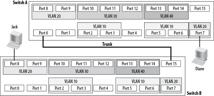
Figure 5-1. A trunk connecting two switches
Trunking is generally related to switches, but routers, firewalls, and all manner of devices can connect with trunks as well. The router-on-a-stick scenario described in Chapter 4 requires a router to communicate with a trunk port on a switch.
Figure 5-2 is a visual representation of a trunk. VLANs 10, 20, 30, and 40 exist on both sides of the trunk. Any traffic from VLAN 10 on Switch 1 that is destined for VLAN 10 on Switch 2 must traverse the trunk (of course, the reverse is true as well).
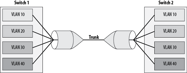
Figure 5-2. Visual representation of a trunk
For the remote switch to determine how to forward the frame, the frame must contain a reference to the VLAN to which it belongs. IP packets have no concept of VLANs, though, nor do TCP, UDP, ICMP, or any other protocol above Layer 2. Remember that a VLAN ...