This chapter provides a brief introduction to assembly language (ASM), in order to lay the groundwork for the reverse engineering chapters in Part I. This is not a comprehensive guide to learning ASM, but rather a brief refresher for those already familiar with the subject. Experienced ASM users should jump straight to Chapter 2.
From a cracker’s point of view, you need to be able to understand ASM code, but not necessarily program in it (although this skill is highly desirable). ASM is one step higher than machine code, and it is the lowest-level language that is considered (by normal humans) to be readable. ASM gives you a great deal of control over the CPU. Thus, it is a powerful tool to help you cut through the obfuscation of binary code. Expert crackers dream in assembly language.
In its natural form, a program exists as a series of ones and zeroes. While some operating systems display these numbers in a hex format (which is much easier to read than a series of binary data), humans need a bridge to make programming—or understanding compiled code—more efficient.
When a processor reads the program file, it converts the binary data into instructions. These instructions are used by the processor to perform mathematical calculations on data, to move data around in memory, and to pass information to and from inputs and outputs, such as the keyboard and screen. However, the number of instruction sets and how they work varies, depending on the processor type and how powerful it is. For example, an Intel processor, such as the Pentium 4, has an extensive set of instructions, whereas a RISC processor has a limited set. The difference can make one processor more desirable in certain environments. Issues such as space, power, and heat flux are considered before a processor is selected for a device. For example, in handheld devices, a RISC-based processor such as ARM is preferable. A Pentium 4 would not only eat the battery in a few minutes, but the user would have to wear oven mitts just to hold the device.
While it is possible for a processor to read and write data directly from RAM, or even the cache, it would create a bottleneck. To correct this problem, processors include a small amount of internal memory. The memory is split up into placeholders known as registers . Depending on the processor, each register may hold from 8 bits to 128 bits of information; the most common is 32 bits. The information in a register could include a value to be used directly by the processor, such as a decimal number. The value could also be a memory address representing the next line of code to execute. Having the ability to store data locally means the processor can more easily perform memory read and write operations. This ability in turn increases the speed of the program by reducing the amount of reading/writing between RAM and the processor.
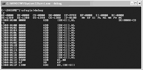
In the typical x86 processor, there are several key registers that you
will interact with while reverse engineering. Figure 1-1 shows a screenshot of
the registers on a Windows XP machine using the debug -r command (the -u command provides a disassembly).
The following list explains how each register is used:
- AX
Principle register used in arithmetic calculations. Often called the accumulator, AX is frequently used to accumulate the results of an arithmetic calculation.
- BX (BP)
The base register is typically used to store the base address of the program.
- CX
The count register is often used to hold a value representing the number of times a process is to be repeated.
- DX
The data register value simply holds general data.
- SI and DI
The source and destination registers are used as offset addresses to allow a register to access various elements of a list or array.
- SS, CS, ES, and DS
The stack segment, code segment, extra segment, and data segment registers are used to break up a program into parts. As it executes, the segment registers are assigned the base values of each segment. From here, offset values are used to access each command in the program.
- SP
Holds the stack pointer address, which is used to hold temporary values required by a program. As the stack is filled, the SP changes accordingly. When a value is required from the stack, it is popped off the stack, or referenced using an SP + offset address.
- IP
The instruction pointer holds the value of the next instruction to be executed.
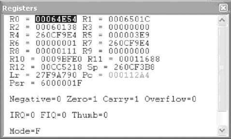
This list of registers applies only to x86. While there are many similarities, not all processors work in the same way. For example, the ARM processor used in many handheld devices shares some of the same register types, but under different names. Take a look at Figure 1-2 to see examples of ARM registers. (ARM reverse engineering is covered in Chapter 4.)
In Part I of this book, you will learn how these registers are used, and also how they can be abused in order to perform attacks such as buffer overflows. It is important to be very familiar with how registers work. While reverse engineering, you can spend up to 80% of your time reading the values in registers and deducing what the code will do or is doing as a result of these values.
The amount of data a processor can hold locally within its registers is extremely limited. To overcome this limitation, memory from RAM (or the cache) is used to hold pieces of information required by the program.
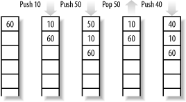
The stack is nothing more than a chunk of RAM that stores data for use by the processor. As a program needs to store information, data is pushed onto the stack. In contrast, as a program needs to recall information, it is popped off the stack. This method of updating the stack is known as last in, first out. To illustrate, imagine a stack of those free AOL CD-ROMs that make great coasters. As you receive new ones in the mail, they get placed on the top of the stack. Then, when you need a disposable coaster, you remove the freshest CD from the top of the stack.
While the stack is simply used to hold data, the reason for its existence is more complex. As a program executes, it often branches out to numerous subroutines that perform small functions to be used by the main program. For example, many copy-protection schemes perform a serial number check when they are executed. In this case, the flow of the program temporarily branches to verify that the correct serial number was entered. To facilitate this process, the address of the next line of code in the main program is placed onto the stack with any values that will be required once the execution has returned. After the subroutine is complete, it checks the stack for the return address and jumps to that point in the program.
It is important to note that due to the last in, first out operation of the stack, procedures can call other procedures that call yet more procedures, and the stack will still always point to the correct information. As each procedure finishes, it pops off the stack the value that it had previously pushed on. Figure 1-3 illustrates how the stack is used.
It is important to be familiar with concepts of addressing when performing reverse engineering. For example, in the ARM processor, loading data from the stack is often done using an offset. Without understanding how the offset is used, or what value in the stack it actually refers to, you could easily become lost. In the case of an ARM processor, the following command loads R1 with the value located at the address of the stack pointer + 8 bytes:
LDR R1, [SP, 0x8]
To add to the confusion, the value loaded into R1 may not even be a true value, but rather a pointer to another location that holds the target value for which you are searching.
There are two main methods for explicitly locating an address. The first is the use of a segment address plus an offset. The segment address acts as a base address for a chunk of memory that contains code or values to be used by a program. For a more direct approach, a program could also use an effective address, which is the actual address represented by a segment + offset address.
As we previously discussed, a program uses several key registers to keep track of data and the flow of execution. When these registers are used together, the processor has instant and easy access to a range of data. For example, the BX register is often used to store a base address. This address is used as a defined point in memory from which values can be called. For instance, if a program needs access to an array or a list of data in memory, then BX could be set to the beginning of that list. Using the BX address combined with an SI or DI value, the full list of values could be accessible to the processor using a BX+DI reference. If that is not enough control, you could also access an element in an array using an offset such as BX+DI+8. As you can see, addressing can be confusing unless you have a firm understanding of how registers are used.
Now that you understand registers and how memory is accessed, here’s a quick overview of how opcodes are used. This is a brief summary only, since each processor type and version will have a different instruction set. Some variations are minor, such as using JMP (jump) versus B (branch) to redirect the processor to code in memory. Other variations, such as the number of opcodes available to the processor, have a much larger impact on how a program works.
Opcodes are the actual instructions that a program performs. Each opcode is represented by one line of code, which contains the opcode and the operands that are used by the opcode. The number of operands varies depending on the opcode. However, the size of the line is always limited to a set length in a program’s memory. In other words, a 16-bit program will have a 1-byte opcode and a 1-byte operand, whereas a 32-bit program will have a 2-byte opcode and a 2-byte operand. Note that this is just one possible configuration and is not the case with all instruction sets.
As stated previously, the entire suite of opcodes available to a
processor is called an instruction set. Each processor requires its own
instruction set. You must be familiar with the instruction set a
processor is using before reverse engineering on that device. Without
understanding the vagaries among opcodes, you will spend countless
hours trying to determine what a program is doing. This can be quite
difficult when you’re faced with such confusing opcodes as UMULLLS R9, R0,
R0, R0 (discussed in Chapter 4). Without first being
familiar with the ARM instruction set, you probably would not guess
that it performs an unsigned multiply long if the LS status is set,
and then updates the status flags accordingly after it
executes.
One final note: when programs are disassembled, the ASM output syntax may vary according to the disassembler you are using. A particular disassembler may place operands in reverse order from another disassembler. In many of the Linux examples in this book, the equivalent command:
mov %edx,%ecx
on Windows reads:
mov ecx,edx
because of the particular disassemblers mentioned in the text.
The Art of Assembly Langage. (http://webster.cs.ucr.edu/Page_asm/ArtOfAsm.html)
Assembly Language Step-by-Step: Programming with DOS and Linux (with CD-ROM), by Jeff Duntemann. John Wiley & Sons, May 2000.
An Assembly Language Introduction to Computer Architecture: Using the Intel Pentium, by Karen Miller and Jim Goodman. Oxford University Press, March 1999.
IA-32 Intel® Architecture Software Developers Manual. (http://www.intel.com/design/Pentium4/manuals/24547012.pdf)
Intel® XScale™ Microarchitecture Assembly Language Quick Reference Card. (http://www.intel.com/design/iio/swsup/11139.htm)
Get Security Warrior now with the O’Reilly learning platform.
O’Reilly members experience books, live events, courses curated by job role, and more from O’Reilly and nearly 200 top publishers.


