16.9 USE OF STG TO DESIGN INTERCONNECTION CIRCUITS
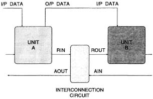
Consider a typical interconnection circuit shown in Fig. 16.42, where the 2 units A and B are connected in a pipeline. The handshake circuit enables the unit A to process the next data sample while the unit B processes the current data sample. Since unit B might take longer to finish or vice versa, an acknowledge signal is necessary to indicate when B has completed its task and is ready for the next data sample. The purpose of the handshake circuit is to ensure correct transmission of data samples and prevent any run away (overwriting of data) conditions.
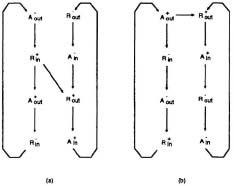
There are two styles of interconnection circuits as shown in Fig. 16.43 [14], differing in their specifications relating the input and output signals. The specification for the STG in Fig. 16.43(a) is
![]()

Fig. 16.42 An example of an interconnection circuit.

Fig. 16.43 Two different specifications of interconnect circuits.
and for that in Fig. 16.43(b) is
![]()
The first condition means that if the input sample is ready (), then start computation (). The requirement that the succeeding ...
Get VLSI Digital Signal Processing Systems: Design and Implementation now with the O’Reilly learning platform.
O’Reilly members experience books, live events, courses curated by job role, and more from O’Reilly and nearly 200 top publishers.

