This chapter covers the configuration of the basic components of Windows Server TCP/IP networking. Installing and configuring other aspects of Windows Server networking—the Remote Access Service, Active Directory, Domain Name Service, Dynamic Host Configuration Protocol, and so on—are covered in later chapters. You use the procedures described in this chapter when you install Windows Server 2003, but you can return to them later to make changes to your network configuration.
Typically, the majority of the computers on a network obtain the network configuration from a DHCP server. In Chapter 5 we look at how to install and configure a DHCP server so that you can provide the TCP/IP configuration for the bulk of systems on the network. However, it is important for a network administrator to know how to set and change the configuration values directly, both because it is a basic skill that every network administrator must have and because there are always some number of systems that require direct configuration.
Not only is the how of basic configuration covered, this chapter also covers the what and why. What configuration values are required and why specific values are selected are discussed.
During the initial Windows Server 2003 installation, the Network Settings window appears. It presents two choices:
Use the “Typical settings” selection to obtain the configuration via DHCP. Most clients use this setting. As a network administrator, it is your job to ensure that the clients obtain the correct configuration from DHCP, as described in Chapter 5.
Use the “Custom settings” selection to manually define the configuration for the system. Custom configuration is the focus of this chapter.
Selecting “Custom settings” opens the “Networking components” window. (This window is almost identical to the one shown in Figure 4-3.) Highlight a component and select Properties to configure that component. For example, highlighting Internet Protocol (TCP/IP) and selecting Properties allows you to set the host’s IP address, to define the IP addresses of the DNS servers, and more. (The window opened by highlighting Internet Protocol (TCP/IP) and selecting Properties during the initial installation is the same as the window shown in Figure 4-5.)
Of course, initial installation is not the only time you might want to define or modify the configuration for a network interface. To configure the interface for a running system, open the Network Connections applet in the Control Panel. You can use the New Connections Wizard to add a new interface configuration. To modify the configuration of an existing interface, select that interface from the Network Connections menu.
Tip
By default, the first Ethernet interface is called Local Area Connection. The second Ethernet interface is named Local Area Connection 2, the third is named Local Area Connection 3, and so on. If your system has interface names of this type, you can rename the interfaces to something more meaningful in exactly the same way that you would rename a file. Simply right-click on the interface in the Network Connections menu, select Rename from the right-click menu, and enter a new, more descriptive name.
Selecting a network interface from the Network Connections menu opens the Adapter Status window , which contains two tabs: General and Support. Selecting the Support tab shows the current interface configuration and states whether it was manually entered or provided by DHCP. Figure 4-1 shows the Support tab.
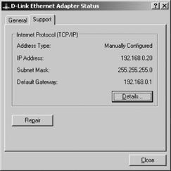
The system shown in Figure 4-1 was manually configured. Clicking the Repair button on a manually configured computer causes the system to flush various network caches and to reregister with DNS and WINS, if that is appropriate. If this system had been configured using DHCP, clicking Repair would do the same things done for a manually configured system and, in addition, would cause the system to renew its address lease.
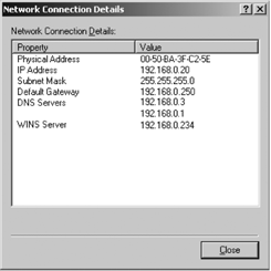
Clicking the Details button on the Support tab shows a few more details of the configuration. Figure 4-2 shows the Network Connection Details window opened by the Details button.
The General tab of the Adapter Status window tells you whether or not the interface is running, how long it has been running, its rated speed, and the number of packets sent and received by the interface. This tab has two buttons:
Use the Disable button to down the interface. This can be useful during troubleshooting. Normally, of course, the interface is left up and running. To reenable the interface after it has been disabled, simply select the interface from the Network Connections menu and it will automatically be reenabled. Disabling and reenabling the interface resets the connection time and the number of packets sent and received.
Use the Properties button to reconfigure the interface.
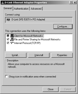
The Properties button opens the Adapter Properties window , which has three tabs:
- Advanced
This tab allows you to select the Internet Connection Firewall (ICF). When you select the checkbox, the Settings button becomes active, which allows you to select the level of security logging the system will use, the types of services that will be offered to remote users, and the types of ICMP packets to which the system will respond. The ICF is covered in Chapter 9.
- Authentication
This tab allows you to select and configure IEEE 802.1X authentication. One of the configuration parameters is the type of Extensible Authentication Protocol (EAP) that will be used. Configuring authentication, including EAP, is covered in Chapter 8.
- General
This tab allows you to configure the network adapter device driver and the network protocols used by this interface. This is the focus of this chapter.
Figure 4-3 shows the General tab of the Adapter Properties window.
Clicking the Configure button opens a window that allows you to configure the network adapter hardware.
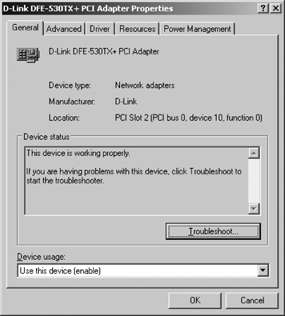
The level of hardware configuration offered depends upon the capabilities of the hardware and the associated device driver. The tabs displayed will vary from device to device. Figure 4-4 shows an example for a specific D-Link Ethernet card.
The properties window shown in Figure 4-4 displays five tabs. The Advanced tab lists configuration properties specific to this device. Another Ethernet card would have different settings on the Advanced tab, if it offered an Advanced tab at all. The Driver tab displays information specific to the driver for this device. The information displayed on the Driver tab varies from manufacturer to manufacturer. However, the essential buttons on this tab should be the same for any network device. The key Driver tab buttons are as follows:
- Update Driver
This button starts the Hardware Update Wizard . Use it to install a new driver for this device.
- Rollback Driver
Use this button to return to the previously installed driver if the new driver does not function properly.
- Uninstall
Use this button only if you intended to completely remove the driver for this device. Do not use this to simply disable the device. As noted earlier, and as we’ll see again, there are simpler ways to temporarily disable a device.
Windows Server 2003 ships drivers for numerous network adapter cards bundled with the operating system. The drivers are of high quality, but things change. Bugs are discovered and drivers are improved. Because of these changes you may find yourself clicking the Update Driver button. Before you do, make sure you have the latest driver available for your adapter:
Check the adapter card manufacturer’s web site for the latest released version of a production driver. Make sure you don’t unintentionally get a beta or unsupported version of the driver. These are commonly posted, but they should only be installed on a production server after a very thorough evaluation.
If you don’t find a suitable driver on the manufacturer’s web site, check the Microsoft web site for the latest version of the Microsoft driver for your adapter. Microsoft drivers are nearly always stable and fast, although they may not implement some special features supported by the manufacturer’s driver, in particular management functions.
If you use Windows Update, it can automatically notify you when a new driver is available for your network adapter.
The General, Resources, and Power Management tabs shown in Figure 4-4 are more generic than the Driver tab. The Power Management tab is there for devices that support Advanced Power Management (APM). APM allows for two-way power control:
The PC can shut off the device to conserve power when the device is not in use. This is generally not an important feature for Ethernet cards because they consume very little power.
The device can bring the PC out of standby mode. This is a more interesting feature for a network device. When the user leaves work and places the PC in a low-power standby mode, this feature allows the PC to continue collecting data from the network. Of course, this feature only saves power if the PC is normally left running at full power in order to collect data from the network.
The Resources tab lists the hardware resources used by the network device and notifies you if any hardware conflicts exist. PC adapter cards require up to four distinct hardware configuration parameters. The parameters are the Interrupt Request number (IRQ), Direct Memory Access (DMA) Direct Request number (DRQ),[*] I/O Port Address (or I/O Range), and Adapter Memory Address.
Of the four configuration values, IRQ assignment traditionally caused the most trouble because there were a limited number of interrupts and interrupts could not be shared. Interrupts on the original PC bus were edge triggered, which means that the transition of the signal on the IRQ line caused the system to detect an interrupt. (Specifically, IBM defined the signal as a transition from low to high.) An IRQ could not be reliably shared because when more than one card attempted to use a single IRQ line the interrupt could be lost.
The Peripheral Component Interconnect (PCI) bus has, by and large, eliminated this problem. The PCI bus is an intelligent bus that supports automatic adapter configuration through Plug and Play (PnP). With PnP, the adapter, the bus and the operating system cooperate to find and assign unused hardware values, thus eliminating conflicts. The NTDETECT.COM software collects the hardware information for the Windows Server 2003 system.
If a conflict is found, the Resources tab lists the device that conflicts with the network adapter. One possible cause of a conflict is an adapter that allows manual configuration that has been incorrectly configured. The problem is not necessarily in the network card. It could be caused by misconfiguration of the conflicting adapter.
The General tab identifies the device, displays the current device status, and allows you to select the “Device usage,” which can be either enable or disabled—yet another way to disable the interface. (Disabling the device via the “Device usage” drop-down box has exactly the same effect as disabling the interface through the Disable button described in the previous section of this chapter.) If the device status is not “This device is working properly,” you can click on the Troubleshoot button, which opens the Help and Support Center window. This is the same Help and Support Center that is available from the Start menu. The difference is that when you enter the Help and Support Center using the Troubleshoot button shown in Figure 4-4, the Help and Support Center has already been primed with the problem: “I’m having a problem with my hardware device.” While not as generic as the Help and Support Center window invoked from the Start menu, it is still not specific to network troubleshooting or even troubleshooting network hardware. See Chapter 14 for network-oriented troubleshooting advice.
Network adapters do not need any manual configuration for most systems. Most of the time, Windows Server 2003 correctly identifies the adapter and installs a properly configured driver for the adapter. The Configure button is useful but rarely needed.
Refer back to Figure 4-3. The window in the middle of the properties dialog shown in Figure 4-3 lists the network components used for the network connection. Three network components are listed:
- Client for Microsoft Networks
This is the client side of the NetBIOS protocol discussed in Chapter 3.
- File and Printer Sharing for Microsoft Networks
This includes the server side of NetBIOS and both the Server Message Block (SMB) protocol and the Common Internet File System (CIFS) protocol. All three of these are described in Chapter 3.
- Internet Protocol (TCP/IP)
This is the Transmission Control Protocol/Internet Protocol suite described in Chapters 1 and 2. This is the protocol we will be manually configuring in this chapter.
Directly under the list of network components are three buttons: Install, Uninstall, and Properties. Click the Install button to install a network component. The Install button opens the Select Network Component Type window. Three component types are offered:
- Client
A client component is the client side of some network service. The Client for Microsoft Networks component described above is one example. Another one offered by default on a Windows Server 2003 system is the Client Service for NetWare.
- Service
A service component is the server side of a network service. For example, the File and Printer Sharing for Microsoft Networks component is a service component. Highlighting Service in the Select Network Component Type window and clicking Add, opens the Select Network Service window. By default, it lists only three components: Network Load Balancing, QoS Packet Scheduler, and Service Advertising Protocol. All three of these components are enhancements to the basic TCP/IP protocol , and none of the three pops to mind when one thinks of a network service. Most network administrators think of services such as DHCP or DNS when they think of TCP/IP services. Services such as DHCP and DNS are installed through the Manage Your Server window, not through the Select Network Service window. (DHCP and DNS installation and configuration are covered in subsequent chapters.)
- Protocol
A protocol component is a network communications protocol. For example, the Internet Protocol (TCP/IP) component described earlier is a protocol component. Of course, the client and service components also contain protocol elements, so the distinction is somewhat arbitrary. In general, protocol components are lower layer protocols upon which client/service protocols are built—but not always. By default, the Select Network Protocol window offers the following five protocol component selections:
- AppleTalk Protocol
This is the AppleTalk protocol used by Apple computers.
- Microsoft TCP/IP version 6
This is the IPv6 protocol described in Chapter 2.
- Network Monitor Driver
This is packet capture software required by the Netmon application.
- NWLink IPX/SPX/NetBIOS Compatible Transport Protocol
This is the Microsoft implementation of the Novell IPX/SPX protocols that are used by NetWare.
- Reliable Multicast Protocol
This is a reliable transport protocol for multicast messages that can be used only by Microsoft Message Queuing (MSMQ).
If you install a component that you don’t need, it is easily removed. The Uninstall button removes an unneeded network component. To remove a component, simply highlight the component name in the list box and click Uninstall. You will be asked to verify the removal. Click Yes and the network component is removed. Any network component can be removed in this manner except for TCP/IP , which is always required.
The Properties button is used to configure a protocol. Protocol configuration is the principal topic of this chapter.
TCP/IP is configured automatically by a DHCP server or manually through the Internet Protocol (TCP/IP) Properties dialog. The Internet Protocol (TCP/IP) Properties dialog is accessed by highlighting the Internet Protocol (TCP/IP) network component on the General tab of the adapter properties window, which is shown in Figure 4-3, and by then clicking the Properties button. The remainder of this chapter is about the Internet Protocol (TCP/IP) Properties window and how it is used to configure TCP/IP.
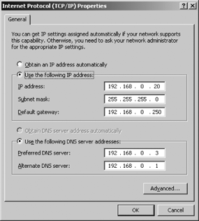
Figure 4-5 shows the General tab of the Internet Protocol (TCP/IP) Properties dialog. This tab is used to manually define the basic configuration or to select automatic configuration from the DHCP server. DHCP is a key component of a manageable, reliable, and efficient network. Therefore you should configure as many systems as possible by selecting the “Obtain an IP address automatically” option button. This is, in fact, the default configuration created by the Windows Server 2003 installation unless the “Custom settings” option in selected during the installation.
Despite the label on this option button, it does much more than just obtain the IP address automatically. The DHCP server provides the complete TCP/IP configuration . Nothing remains to be done because everything can be provided by the DHCP server when the DHCP server is properly configured. Of course, as the administrator of the network it is your responsibility to set up the DHCP server as described in Chapter 5. But your work relieves end users of configuration responsibilities and reduces the number of user configuration errors that you have to fix. The configuration steps described in the next section are not needed for the majority of systems on a network that uses DHCP.
Unfortunately, not every Windows system can use a DHCP server for its configuration. Some systems don’t have access to a DHCP server. Also a DHCP server itself cannot be configured by DHCP, and the administrators of other servers often choose not to configure their systems via DHCP. To configure a system without using DHCP, select the “Use the following IP address” option button, and complete the configuration manually. Below are the manual configuration fields on the IP address portion of the General tab:
- IP Address
Enter a valid IP address for this computer, using dotted decimal format. This is a single address from your address range. The section “Selecting an IP address block” provides advice on defining an address range for your network if you are creating a completely new network.
- Subnet Mask
Enter the appropriate subnet mask, again using dotted decimal format. By default, this field will use the natural mask for the address entered above. If you subnet, you should place your subnet mask here. If you do not subnet, use the prefix-length assigned with the address block to determine the mask. Chapter 2 covers subnets and address masks.
- Default Gateway:
Enter the IP address for the default router in dotted decimal format. Chapter 2 provides background on routing and the use of default gateways, and there is more on routing and gateways later in this chapter.
Of course, before manually entering data into any of these fields you must know exactly what you are going to enter. The network administrator is responsible for making and communicating decisions about overall network configuration. If you’re adding a system to an existing network, you can simply provide the correct values to the person configuring the system from the range of values valid for your network. If you are creating a new network, you will have to make some basic decisions. One of these decisions is how to choose a network number for your new network, which is the topic of the next section. If you already have IP addresses for your network, you can skip this section.
First, you must decide how many hosts on a new network will be fully accessible from the Internet. Many new networks attach to the Internet indirectly so that access into the new network from other Internet networks is limited. An example of an indirectly attached network is a TCP/IP network that attaches to the outside world via a firewall or network address translation (NAT) device. Users on the new network can access remote Internet hosts but remote users cannot directly access all of the hosts on the indirectly connected network. Because the hosts on this network are not accessible to users in the outside world, they do not require public IP addresses. (Only the subset of systems exposed to the outside world requires public IP addresses.) Therefore, the network administrator of this network can select a network address from RFC 1918, Address Allocation for Private Internets. The private network numbers are 10.0.0.0, 172.16.0.0 to 172.31.0.0, and 192.168.0.0 to 192.168.255.0. The pros and cons of using a network address from RFC 1918 are covered in Chapter 2, where private network numbers are discussed in detail. But, in general, if you can use a private network number, you should.
Some organizations choose to give every device on the network an address that will make that device fully accessible from the Internet. A network that wants to be fully accessible from all sites on the Internet must obtain a public network address to allow outside users direct access into the systems on your network. An official address is needed for every system on the network that is directly accessible to remote Internet hosts. Every network that communicates with the Internet, even those that use NAT, has at least one public address, although that address may be assigned to the NAT box. To make many or all of the systems on your network accessible, you need a block of addresses. The first step toward obtaining a block of addresses is to determine how many addresses you need.
Determining your “organizational type” helps you assess your address needs and how you should satisfy those needs. RFC 2901, Guide to Administrative Procedures of the Internet Infrastructure, describes four different organizational types:
- Internet end-user
A small- to medium-sized organization focused on connecting itself to the Internet. This could be as small as a single user connecting to the Internet with a dynamic address assigned by the ISP’s DHCP server, or as large as a network of thousands of hosts using NAT on the enterprise network and official addresses on a limited number of publicly accessible systems. What categorizes this organizational type is that it wants to use the Internet while limiting the number of systems it makes available to remote users. “Internet end-user” organizations obtain official addresses from their ISP. From the point of view of the Internet, all Internet end-user organizations appear small because they use only a limited number of official addresses.
- High-volume end-user
A medium- to large-sized organization that distributes official addresses to systems throughout its network. This type of organization tends to have a distributed management under which divisions within the overall organization are allowed to make systems remotely accessible. High-volume end-user organizations usually satisfy their address requirements through their ISP or a Local Internet Registry. If the organization needs more than 8,000 addresses, it may go directly to a Regional Internet Registry. While in reality a high-volume end-user organization may not be any larger than an Internet end-user organization, it appears to be larger from the point of view of the Internet because it exposes more systems to the Internet.
- Internet Service Provider
An organization that provides Internet connection services to other organizations and provides those organizations with official addresses. Even an ISP connects to the Internet in some way. If it connects through another ISP, that ISP is its upstream provider. The upstream provider assigns addresses to the ISP. If it connects directly to a network access point (NAP), the ISP requests addresses from the Local Internet Registry or the Regional Internet Registry.
- Local Internet Registry
An organization that provides addresses to ISPs. In effect a Local Internet Registry is an organization that provides addresses to other organizations that provide addresses. A Local Internet Registry must obtain its addresses from a Regional Internet Registry.
RFC 2901 lists four organizational types in order to be thorough. Most organizations are either Internet end users or high-volume end users. In all likelihood, your organization is one of these, and you will obtain all of your addresses from your ISP.
Your ISP has been delegated authority over a group of network addresses and should be able to assign you a network number. If your local ISP cannot meet your needs, perhaps the ISP’s upstream provider can. Ask your local ISP whom it receives service from and ask that organization for an address. If all else fails, you may be forced to go directly to an Internet registry. If you are forced to take your request to a registry, you will need to take certain steps before you make the application.
You need to prepare a detailed network topology. The topology must include a diagram that shows the physical layout of your network and highlights its connections to the Internet. You should include network engineering plans that, in addition to diagramming the topology, describe:
Your routing plans, including the protocols you will use and any constraints that forced your routing decisions.
Your subnetting plans, including the mask you will use, and the number of networks and hosts you will have connected during the next year. RFC 2050, Internet Registry IP Allocation Guidelines, suggests the following details in your subnet plan:
A table listing all subnets
The mask for each subnet
The estimated number of hosts
A descriptive remark explaining the purpose of each subnet
The biggest challenge is accurately predicting future requirements for addresses. If you have previously been assigned an address block, you may be required to provide a history of how that address block was used. Even if it is not requested by the Internet registry, a history can be a helpful tool for your own planning. Additionally, you will be asked to prepare a network deployment plan. This plan typically shows the number of hosts you currently have that need official addresses and the number you expect to have in six months, one year and two years.
One factor used to determine how much address space is needed is the expected utilization rate. The expected utilization rate is the number of hosts assigned official addresses divided by the total number of hosts possible for the network. The deployment plans must show the number of hosts that will be assigned addresses over a two-year period. The total number of possible hosts can be estimated from the total number of employees in your organization and the number of systems that have been traditionally deployed per employee. Clearly you need to have a global knowledge of your organization and its needs before applying for an official address assignment.
In addition to providing documentation that justifies the address request, obtaining an official address requires a formal commitment of resources. Most address applications require at least two contacts: an administrative contact and a technical contact. The administrative contact should have the authority to deal with administrative issues ranging from policy violations to billing disputes. The technical contact must be a skilled technical person who can deal with technical problems and answer technical questions. Internet registries require that these contacts live in the same country as the organization that they represent. You must provide the names, addresses, telephone numbers, and email addresses of these people. Don’t kid yourself. These are not honorary positions. These people have targets on their backs when things go wrong.
In addition to human resources, you need to commit computer resources. You should have systems set up, running, and ready to accept the new addresses before you apply for official addresses.
When all of the background work is done, you’re ready to present your case to an Internet registry. A three-level bureaucracy controls the allocation of IP addresses:
- IANA
The Internet Assigned Numbers Authority (IANA) allocates large blocks of addresses to regional Internet registries.
- Regional Internet Registry
Regional Internet Registries (IRs) have been given authority by the IANA to allocate addresses within a large region of the world. There are three IRs:
- APNIC
The Asian Pacific Network Information Center (APNIC) has address allocation authority for Asia and the Pacific region.
- ARIN
The American Registry for Internet Numbers (ARIN) has address allocation authority for the Americas.
- RIPE
Reseaux IP Européens (RIPE) has address allocation authority for Europe.
- Local Internet Registry
Local IRs are given authority, either by IANA or by a regional IR, to allocate addresses within a specific area. An example might be a national registry or a registry created by a consortium of ISPs.
No matter how much address space you need, you should start at the bottom of the hierarchy and work your way up. Always start with your local ISP. If they cannot handle your needs, ask them if there is a local IR that can help you. As a last resort, take your request to the regional IR that serves your part of the world.
The most important thing to remember is that most organizations never have to go through this process. Most organizations do not want to expose the bulk of their computers to the Internet. For security reasons, they use private address numbers for most systems and only have a limited number of official IP addresses. That limited number of addresses can usually be provided by a local ISP.
One final note, when you obtain a block of official IP address, you may also need to apply for an in-addr.arpa domain This special domain is sometimes called a reverse lookup domain. Chapter 6 contains more information about how the in-addr.arpa domain is set up and used, but basically the reverse lookup domain maps numeric IP addresses into domain names. This is the reverse of the normal domain name lookup process, which converts domain names to addresses. If your ISP provides your name service or your ISP assigned you an address from a block of its own addresses, you probably do not need to apply for an in-addr.arpa domain. Check with your ISP before applying. If, however, you obtain a block of addresses from a Regional IR, you probably will need to register your own in-addr.arpa domain. If you do need to get a reverse lookup domain, register it with the same organization from which you obtained your address assignment.
Again, the most important thing to note about reverse address registration is that most organizations don’t have to do this. If you obtain your address from your ISP, you probably do not have to take care of this paperwork yourself. These services are one of the reasons you pay your ISP.
Refer to Figure 4-5. The lower half of the General tab of the Internet Protocol (TCP/IP) Properties window defines the IP addresses of two DNS servers . If the “Obtain an IP address automatically” checkbox is selected, you will be offered the opportunity to select the Obtain DNS server address automatically checkbox. This means that if you obtain the host’s IP address from the DHCP server, you have the option of either obtaining the DNS server address from DHCP or entering the DNS server address manually. However, if you enter the host IP address manually, you must also enter the DNS server address manually.
Two DNS server addresses can be entered in this window:
- Preferred DNS server
The preferred DNS server is simply the server to which this system should first direct DNS queries. It is not necessarily the same system as the primary (or master) DNS server for your domain. In fact, it probably is not. (See Chapter 3 for information on DNS server types.) Most often, this is the address of the DNS server that is topographically the closest to the system being configured, which is frequently a server located on the same local network as the host.
- Alternate DNS server
The alternate DNS server is a backup server. This server is only queried when the preferred DNS server fails to respond to a query. The alternate server provides reliability for those times when the preferred server is offline. Frequently, an authoritative server, such as the primary or a secondary server for the local domain, is specified here because, given the importance of the authoritative servers, it is highly unlikely that the authoritative servers will be offline when the local DNS server is down. Another factor to consider when picking an alternate server is reachability. In general, it is a good idea to pick preferred and alternate DNS servers that are reached through different network paths so that the servers are less vulnerable to a network outage.
The General tab creates a minimal configuration . There are, of course, more TCP/IP configuration options than the few shown on the General tab. We will examine these additional configuration options in the following sections.
Note the Advanced button near the bottom of the General tab shown in Figure 4-5. Click the Advanced button to display the Advanced TCP/IP Settings window. The IP Settings tab of this window is shown in Figure 4-6.
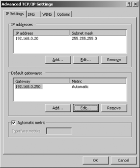
The default Advanced TCP/IP Settings window contains four tabs:
- IP Settings
This tab defines additional IP addresses with their associated subnet masks, and it defines additional routers.
- DNS
This tab defines additional DNS server addresses and the value used to fully qualify unqualified domain names when constructing DNS queries.
- WINS
This tab defines the WINS server addresses and options for NetBIOS name resolution.
- Options
By default, the only option this tab provides access to is “TCP/IP filtering.”
The Advanced TCP/IP Setting window has two buttons at the bottom: OK and Cancel. These buttons are global to all tabs in the window. Do not click on OK until you have completed all tabs. Clicking on OK exits the TCP/IP configuration process, perhaps before you have finished. Similarly, clicking Cancel discards the changes, not just to the page currently displayed but to all pages.
Windows Server 2003 allows you to assign multiple IP addresses to a single physical network adapter. This is useful, for example, if you want to run multiple subnets on the same physical network. We’ll see a use for this in the discussion of superscopes in Chapter 5.
Add IP addresses to a network adapter by clicking Add in the “IP addresses” pane to display the TCP/IP Address dialog box. In the dialog, enter the IP address and its associated netmask. Windows defaults the subnet mask to the natural mask of the IP address you entered. If the IP address is part of a block with a specifically assigned prefix-length or is a member of a subnet, the correct value must be entered manually. Always verify that the subnet mask is correct to avoid connectivity problems that can be extremely difficult to resolve.
Highlight an address in the “IP addresses” pane and click Edit to modify an existing IP address and subnet mask. Remove an IP address by highlighting it and clicking Remove.
Windows Server 2003 allows you to define multiple default
gateways through the Add button in the “Default gateways” pane
of the IP Settings tab. (Refer back to the IP Settings tab in Figure 4-6.) Clicking the
Add button displays the TCP/IP Gateway Address dialog box. In the
dialog, enter the IP address of the gateway and select the routing
metric that you want to assign to this route. You can either check the
“Automatic metric” checkbox to allow Windows to assign the metric, or
you can uncheck that box and manually enter a numeric value for
Metric. The automatic metric is determined by the characteristics of
the network interface. Therefore when multiple routers are added
through the “Default gateways” pane of the same IP Settings tab, they
are all given the same automatic metric because they are all
associated with the same interface. The following route print command shows an example of
this:
    D:\>route print
    IPv4 Route Table
    ===========================================================================
    Interface List
    0x1 ........................... MS TCP Loopback interface
    0x10003 ...00 50 ba 3f c2 5e ...... D-Link DFE-530TX+ PCI Adapter
    ===========================================================================
    ===========================================================================
    Active Routes:
    Network Destination        Netmask          Gateway       Interface  Metric
              0.0.0.0          0.0.0.0    192.168.0.250     192.168.0.20     20
              0.0.0.0          0.0.0.0      192.168.0.1     192.168.0.20     20
            127.0.0.0        255.0.0.0        127.0.0.1        127.0.0.1      1
          192.168.0.0    255.255.255.0     192.168.0.20     192.168.0.20     20
         192.168.0.20  255.255.255.255        127.0.0.1        127.0.0.1     20
        192.168.0.255  255.255.255.255     192.168.0.20     192.168.0.20     20
            224.0.0.0        240.0.0.0     192.168.0.20     192.168.0.20     20
      255.255.255.255  255.255.255.255     192.168.0.20     192.168.0.20      1
    Default Gateway:     192.168.0.250
    ===========================================================================
    Persistent Routes:
      None
The details of the routing table are explained in Chapter 2. In this case, we are only interested in the first two active routes. They both are default gateways as indicated by the fact that they both have destinations and netmasks of 0.0.0.0. Both of these gateways were entered into the configuration through configuration windows associated with the D-Link Ethernet interface on this sample system. (The interface is assigned the IP address 192.168.0.20.) The first gateway—the one assigned address 192.168.0.250—was defined in the “Default gateway” box of the General tab of the Internet Protocol (TCP/IP) Properties window for this interface, as shown in Figure 4-5. The second gateway was defined through the Add button of the “Default gateways” pane of the IP Settings tab shown in Figure 4-6. When it was defined, the “Automatic metric” checkbox was used. Both routes are associated with the same interface, and both have the same metric. Given the routing table shown above, the system will attempt to use default gateway 192.168.0.250 first because it is listed first in the table and has the same metric as the other default gateway.
Tip
This discussion is only about default gateways. If a specific route to a destination is included in the routing table, it is always preferred over the default route for packets addressed to that specific destination.
Both of the default gateways in the table shown above are
reached through the same interface (192.168.0.20), therefore, they are
automatically assigned the same metric. To use a different metric,
manually enter the metric in the Metric box of the TCP/IP Gateway
Address dialog when adding a default gateway. In the routing table
shown below, a metric of 5 was
manually entered for the 192.168.0.1 default router:
    D:\>route print

    IPv4 Route Table
    ===========================================================================
    Interface List
    0x1 ........................... MS TCP Loopback interface
    0x10003 ...00 50 ba 3f c2 5e ...... D-Link DFE-530TX+ PCI Adapter
    ===========================================================================
    ===========================================================================
    Active Routes:
    Network Destination        Netmask          Gateway       Interface  Metric
              0.0.0.0          0.0.0.0    192.168.0.250     192.168.0.20     20
              0.0.0.0          0.0.0.0      192.168.0.1     192.168.0.20      5
            127.0.0.0        255.0.0.0        127.0.0.1        127.0.0.1      1
          192.168.0.0    255.255.255.0     192.168.0.20     192.168.0.20     20
         192.168.0.20  255.255.255.255        127.0.0.1        127.0.0.1     20
        192.168.0.255  255.255.255.255     192.168.0.20     192.168.0.20     20
            224.0.0.0        240.0.0.0     192.168.0.20     192.168.0.20     20
      255.255.255.255  255.255.255.255     192.168.0.20     192.168.0.20      1
    Default Gateway:     192.168.0.250
    ===========================================================================
    Persistent Routes:
      None
The metric defines the order of precedence among routers that can reach the same destination. The lower the metric, the lower the cost, and thus the more preferred the route. Given the routing table shown above, the system will attempt to use default gateway 192.168.0.1 first because it has the lowest metric, even though it is not the first default gateway listed in the table.
When multiple gateways are defined for a single destination, only one gateway is active at any one time. Windows Server 2003 uses the gateway with the lowest metric. If multiple gateways have the same metric, Windows uses the first gateway listed. Only if the preferred gateway is down or otherwise not accessible does it attempt to use additional gateways.
Specifying multiple default gateways has limited utility because it requires that more than one router be directly attached to the same local network as the host, and that more than one of those routers be capable of reaching all destinations. In many cases where there is more than one router on the network some of the routers only reach other internal networks and therefore are not suitable to be default routers.
Don’t try to use the “Default gateways” pane to build complex
static routes. It is simply not flexible enough because it can only be
used to define default gateways. If static routes are required, use
the route command, which is
available through the Windows Server 2003 command interface. It lets
you manually configure the routes in the routing table. The command
syntax is:
route [-f] [-p] [command[destination] [masknetmask] [gateway] [metric metric] [if interface]
The options are used as follows:
-fFlush all of the routes from the routing tables. If used with one of the commands, the table is flushed before the command is executed.
-pCreate a permanent route that is reinstalled in the routing table every time the system boots.
commandThe
commandfield specifies the action that theroutecommand should take. There are four command keywords:addAdd a route.
deleteDelete a route.
changeModify an existing route.
printDisplay the routing table.
destinationThis is the IP address of the network or host that is reached through this route.
masknetmaskThe
netmaskis applied to the address provided in the destination field to determine the true destination of the route. If a bit in thenetmaskis set to1, the corresponding bit in the destination field is a significant bit in the destination address. For example, a destination of 172.16.12.1 with anetmaskof255.255.0.0defines the route to network 172.16.0.0, but the same destination with a mask of255.255.255.255defines the route to the host 172.16.12.1. If no value is specified for thenetmask, it defaults to255.255.255.255.gatewayThis is the IP address of the gateway for this route.
Assume we are configuring a system that has the IP address
192.168.0.20 and that is located on subnet 192.168.0.0. In the
following example we add a route to the host 172.16.12.3 and a route
to the subnet 172.16.8. In each case, the address mask determines if
the route is interpreted as a network route or a host route. After
entering the new routes, we display the routing table with the
route print command to examine our
handiwork:
C:\>route -p add 172.16.12.3 mask 255.255.255.255 192.168.0.1C:\>route -p add 172.16.8.0 mask 255.255.255.0 192.168.0.1 metric 5C:\>route printIPv4 Route Table =========================================================================== Interface List 0x1 ........................... MS TCP Loopback interface 0x10003 ...00 50 ba 3f c2 5e ...... D-Link DFE-530TX+ PCI Adapter =========================================================================== =========================================================================== Active Routes: Network Destination Netmask Gateway Interface Metric 0.0.0.0 0.0.0.0 192.168.0.250 192.168.0.20 20 127.0.0.0 255.0.0.0 127.0.0.1 127.0.0.1 1 172.16.8.0 255.255.255.0 192.168.0.8 192.168.0.20 1 172.16.12.3 255.255.255.255 192.168.0.5 192.168.0.20 1 192.168.0.0 255.255.255.0 192.168.0.20 192.168.0.20 20 192.168.0.20 255.255.255.255 127.0.0.1 127.0.0.1 20 192.168.0.255 255.255.255.255 192.168.0.20 192.168.0.20 20 224.0.0.0 240.0.0.0 192.168.0.20 192.168.0.20 20 255.255.255.255 255.255.255.255 192.168.0.20 192.168.0.20 1 Default Gateway: 192.168.0.250 =========================================================================== Persistent Routes: Network Address Netmask Gateway Address Metric 172.16.12.3 255.255.255.255 192.168.0.1 1 172.16.8.0 255.255.255.0 192.168.0.1 5
As the display shows, there are several more routes than the two we just entered. All of the other routes are part of the basic routing table, which is described in Chapter 2.
The routes we are interested in are both listed in the
Persistent Routes section of the route
print display. Routes added by the route add command will not survive a boot
without the -p option. Use the
-p option when you want to add
permanent static routes to the routing table. The -p option is not used when the routes are
installed for some temporary purpose, such as troubleshooting.
Note that the default metric used with the route command is 1. This is not the same default metric used
by the “Automatic metric” checkbox in the TCP/IP Gateway Address
dialog. The default metric can be overridden on the route command-line
using the metric argument, as in
the example above.
The sample system used in this example has only one network
interface adapter. All of the routes added by the route add command are associated with that
interface. When more than one network interface is available, Windows
selects the default interface for a route based on the gateway address
used for the route. For example, if the gateway address shows that the
gateway is on network 192.168.0.0, Windows will use the network
interface attached to network 192.168.0.0. To manually specify the
interface a route should use, add the if argument to the route command-line. The interface should be
specified by its interface number—not by its IP address. The interface
number is the first field displayed for each interface in the
Interface List section of the routing table. On our sample system, the
interface number associated with the D-Link Ethernet card is 0x10003.
The following route add command
associates the route to network 172.16.81.0 with the D-Link interface
on our sample system:
D:\>route -p add 172.16.81.0 mask 255.255.255.0 192.168.0.8 if 0x10003
Use the route command only
when your system requires complex static routes. Most workstations use
a single default route, allowing that default router to redirect
packets as necessary. Let’s return to the Advanced TCP/IP Settings
window to finish entering configuration data.
An important part of a TCP/IP network is the DNS. The client portion of DNS, which is called the resolver, must be configured on every system. To customize the resolver configuration, select the DNS tab , which is shown in Figure 4-7.
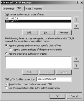
The “DNS server addresses, in order of use” pane, by default, contains the server addresses entered on the General tab of the Internet Protocol (TCP/IP) Properties window, as shown in Figure 4-5. Use the Add button to enter the IP address of any additional DNS servers that you wish to use. Additional DNS servers provide added redundancy, but they rapidly reach a point of diminishing returns. Each server is queried in turn, but only after the server above it in the list fails to respond to the query. Each server is queried multiple times and each query is given a reasonable timeout. These timeouts add up if too many servers are placed in this list, which unnecessarily makes the user wait for the inevitable error message. If the servers are properly chosen, they are not all going to be down at the same time. It is far more likely that multiple servers are unreachable at the same time because of a network problem or a local problem. Adding more servers to the list, cannot fix a network problem. Two well-chosen servers are adequate, and three are probably the most you want. If you cannot contact any of three different well-chosen servers, the problem is not with the remote servers; it is with the network or your local system. Use the Add, Edit, and Remove buttons as needed to configure the list of servers.
Use the up and down arrow buttons to arrange the servers in the order that you want them searched. When Windows needs to resolve an IP address, it starts with the first server on the list. If that server is unavailable, it then tries the second server. If that server fails to respond, Windows continues to try servers in the order they are listed until it either is able to resolve the address or runs out of servers to try.
Two option buttons and a checkbox in the middle of the DNS tab are used to configure how Windows qualifies unqualified hostnames. An unqualified hostname is a hostname without an associated domain name. When the resolver builds a DNS query for an unqualified hostname, the hostname is extended to a fully qualified domain name before the query is passed to the name server. The domain name the resolver appends to the hostname depends on which options are selected.
When the “Append primary and connection specific DNS suffixes” option button is selected, the primary domain name and the domain name associated with this connection are used to fully qualify unqualified hostnames. The domain name associated with the connection is the domain name entered in the “DNS suffix for this connection” box near the bottom of the DNS tab. In Figure 4-7, the sample value entered in this box is sales.example.net. The primary DNS suffix, however, is not configured through this window. It is configured on the Computer Name tab of the System Properties dialog. To configure the primary DNS domain name, go to the Start menu, open the Control Panel menu and select System. In the System Properties window, select the Computer Name tab. Click Change to open the Computer Name Changes window. Then click More to open the DNS Suffix and NetBIOS Computer Name dialog. In the “Primary DNS suffix for this computer” box, enter the primary domain name for this computer. Figure 4-8 shows this dialog.
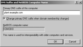
Given the values in Figures 4-7 and 4-8, the primary DNS suffix for this system is plant.example.com, and the DNS suffix for this connection is sales.example.net. The “Append parent suffixes of the primary suffix” checkbox impacts how these domain names are used. If the checkbox had been selected with the settings shown in Figures 4-7 and 4-8, a request for the IP address of mandy generates a query for mandy.plant.example.com, then one for mandy.example.com (assuming the first query was not successful), and finally one for mandy.sales.example.net (assuming the second query was not successful). The system does not, however, search example.net, which is the parent domain of sales.example.net. If the “Append parent suffixes of the primary suffix” checkbox is not selected, a query for mandy would generate a query for mandy.plant.example.com and then one for mandy.sales.example.net. No parent domains would be searched.
Defining your own domain search list is the alternative to using the primary and connection DNS suffixes. To define your own search list, click the “Append these DNS suffixes (in order)” option button. This enables the Add, Edit, and Remove buttons. Click the Add button to add a DNS suffix to the search list. Use the up and down arrows to define the search sequence. Domains are searched in order from the top to the bottom of the list. Figure 4-9 shows an example domain search list.
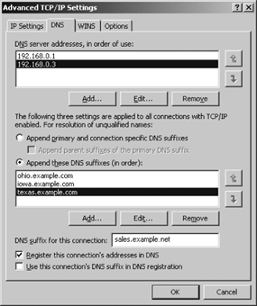
With the configuration shown in Figure 4-9, a query for mandy would generate queries for mandy.ohio.example.com, mandy.iowa.example.com, and mandy.texas.example.com, in exactly that order. No other domains would be searched. Even the domain provided in the “DNS suffix for this connection” box in Figure 4-9 is not searched when an explicit search list is defined. When a search list is provided, it must include all of the domains that you want searched.
Tip
A query is also issued for the name exactly as it is typed in by the user, regardless of what is defined on the DNS tab. The DNS suffixes are only used to extend hostnames so that it is possible for a user to enter the names in a shorter form. They do not interfere with the normal processing of a query.
The two checkboxes at the bottom of the DNS tab configure dynamic DNS. Selecting the “Register this connection’s address in DNS” checkbox causes the system to attempt to register its IP address with DNS using the hostname and domain defined for this system via the Computer Name tab of the System Properties window. The “Use this connection’s DNS suffix in DNS registration” checkbox is active only if the first checkbox is selected. This checkbox causes the system to also register its address using the hostname from the Computer Name tab and the domain name from the “DNS suffix for this connection” box. Of course, these client-side settings are only useful if you have a server running dynamic DNS. Chapter 3 provides more information about dynamic DNS, and Chapter 6 provides information about the server side of dynamic DNS.
The Windows Internet Name Service (WINS) maps NetBIOS names to IP addresses, as described in Chapter 3. The WINS client needs to know the address of the WINS server in order to use the server to register its own name and resolve other NetBIOS names. The WINS client can be configured through DHCP or manually configured through the WINS tab shown in Figure 4-10.
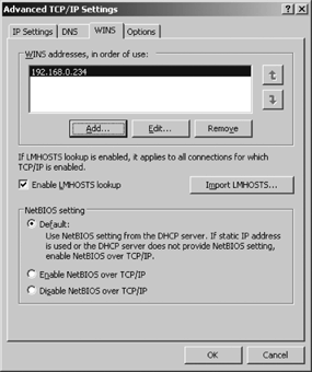
The basic configuration of the WINS client is very straightforward. Use the Add button in the “WINS addresses, in order of use” pane to enter the IP addresses of the WINS servers this client should use. Use the up and down arrows to define the order in which the servers are used for registration and resolution. If no servers are specified in this pane, the client will use broadcasting for registration and resolution. Chapter 3 describes how WINS registration and resolution functions.
Chapter 3 also
describes how the LMHOSTS file is created and
used. Mark the Enable LMHOSTS Lookup checkbox to
use the LMHOSTS file for NetBIOS name resolution.
The LMHOSTS file is located in the
%SystemRoot%\System32\Drivers\Etc folder. Use any
text editor to create an LMHOSTS file based on
the sample file Lmhosts.SAM, also located in this folder. You can
import an existing LMHOSTS file by clicking the
Import LMHOSTS button and browsing for the file.
The function of the Import LMHOSTS button is the
same as that of the #INCLUDE
command that can be placed inside the LMHOSTS
file. See Chapter 3 for a
detailed description of this file.
The three option buttons in the “NetBIOS setting” pane of the WINS tab control whether or not NetBIOS over TCP/IP (NetBT) is enabled, and how it is enabled. The functions of two of these buttons are obvious: “Enable NetBIOS over TCP/IP” manually enables NetBT, and “Disable NetBIOS over TCP/IP” manually disables it. Use these buttons to manually control NetBT without regard to the DHCP configuration. The Default button takes the NetBT setting from DHCP. If DHCP does not provide a NetBT setting or DHCP is not used, the Default option enables NetBT by default. Given the mix of NetBIOS network components and the TCP/IP network component shown in Figure 4-3 for this sample system, we need NetBT. Therefore, we would use either the Default option or the “Enable NetBIOS over TCP/IP” option for this sample configuration.
By default, the Options tab of the Advanced TCP/IP Settings window lists only “TCP/IP filtering” in the “Optional settings” pane. To filter incoming traffic based on ports and protocols, highlight “TCP/IP filtering” and then click Properties to display the TCP/IP Filtering dialog shown in Figure 4-11. Through this dialog Windows Server 2003 allows you to control which TCP ports, UDP ports, and IP Protocols are available to network users.
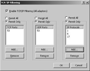
By default, Windows Server 2003 sets Permit All for all three categories. This means that any network user can access any TCP/IP service available on the server. Of course, this default could change with the next service pack.
In Chapter 2 we saw that each port number represents a network service and that each protocol number identifies a protocol that communicates directly with IP. You can control access to a network service or protocol by controlling access to its TCP port, UDP port, or IP protocol. To restrict one of these elements, click the Permit Only option button for that pane, and use the Add and Remove buttons to list only those ports or protocols that users will be permitted to access. Marking the Permit Only option button for a pane and leaving the associated list blank prohibits users from accessing any resources in that category.
The port filtering defined in the TCP/IP Filtering dialog only affects inbound traffic. Figure 4-11 shows a possible configuration for a dedicated DNS server, which is configured to permit only TCP and UDP port 53 (DNS), and only IP protocols, 1 (ICMP), 6 (TCP), and 17 (UDP). With these settings DNS would function normally but other inbound connections would be blocked. For example, this would prevent email from coming into the SMTP port but it would not prevent the administrator of this system from sending email out to some remote server’s SMTP port. Outbound traffic is not affected by these filters.
Tip
The port filtering ability offered by the TCP/IP Filtering dialog is very similar to the inetd.conf port filtering on Unix systems. It is useful in some security situations, though not all. If you need more capability—for example, the ability to filter port ranges or the ability to deny outbound traffic for a particular port—consider installing Microsoft Routing and RAS. The expanded protocol filtering provided by RRAS is covered in Chapter 8. In addition, the Internet Connection Firewall covered in Chapter 9 provides enhanced protocol filtering.
The “Enable TCP/IP Filtering (All adapters)” checkbox, near the top of the TCP/IP Filtering dialog, should be checked. If it is not checked, the filtering configuration you build with this dialog will not be used. The only time the “Enable TCP/IP Filtering (All adapters)” checkbox should be unchecked is during network troubleshooting, and then only for certain problems. If you have a specific network application that is failing, it is possible that you made a mistake when building your TCP/IP filters. Using this checkbox you can temporarily disable the filters and retest the application. If it still fails, the problem is not in the TCP/IP filters. If the application runs with the filter disabled, the problem might be the filter. In that case, you should carefully examine the filter to see if you made a mistake entering port numbers or protocol numbers.
Basic TCP/IP configuration takes place during the initial Windows Server 2003 installation. At any time, however, you can reconfigure the system through the Network Connections applet in the Control Panel. The configuration is entered on a adapter-by-adapter basis.
An alternative to manually defining the TCP/IP configuration is to use DHCP to automatically provide all of the require configuration information. In Chapter 5 we learn how to set up a DHCP server.
Get Windows Server 2003 Network Administration now with the O’Reilly learning platform.
O’Reilly members experience books, live events, courses curated by job role, and more from O’Reilly and nearly 200 top publishers.

