July 2007
Beginner
1326 pages
34h 47m
English
IN THIS CHAPTER
Working with absolute, relative, and polar coordinates
Using direct distance entry, orthogonal mode, and polar tracking
Using snap settings
Working with object snaps (OSNAPS)
Locating points
Specifying points in a drawing is one of the most fundamental tasks you do in AutoCAD and AutoCAD LT. Unless you know how to specify a point, you can't draw anything real, whether a house or a gasket. Most objects you draw have a specific size, and you need to specify that information. You draw lines, arcs, and circles by specifying the coordinates of points on the screen. As with most tasks, AutoCAD and AutoCAD LT offer many ways to accomplish this.
Remember when you studied geometry and trigonometry in high school? You created graphs by drawing X and Y axes. Then you plotted coordinates on graph paper. AutoCAD and AutoCAD LT work the same way.
Look at two displays of the User Coordinate System (UCS) icon, as shown in Figure 4.1. The UCS icon on the left is the default for 2D drawing; the one on the right is the default for 3D drawing and includes the Z axis. In this chapter, I focus on the X and Y axes.
The UCS icon can take on different appearances. See Chapter 8 for details. For information on the UCS icon in 3D work, see Chapter 21.
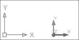
Figure 4.1. The UCS icon shows the direction of the X and Y axes. If you're ...
Read now
Unlock full access


