Chapter 1. Getting Ready
Let’s get right down to business. This chapter offers a shopping guide and an introduction to all the major components you’ll need to prep your networking toolbox with essential parts and programs. There are plenty of options, so we’re going to focus on just what you need to get up and running. Check the Appendix A for a comprehensive list of resources. For now, here are the essentials, distilled for your convenience.
Note
In this book we focus on XBee brand ZigBee radios because they have a host of features that make them especially easy for beginners to work with. Many other brands exist, however most are best suited to those with an electrical engineering background. If that’s you, the resource guide at the end of this book lists other ZigBee options you can consider. Professional engineers often prefer XBees for prototyping or anytime a reduced development effort makes them the most cost-effective option.
Buying an XBee Radio
Digi International manufactures a bewildering array of XBee-branded radios. All told there are at least 30 different combinations of component hardware, firmware protocols, transmission powers, and antenna options. We’ll first take a look at what’s out there, and then narrow that down to the devices we will be using in this book.
Hardware
There are two basic varieties of XBee radio physical hardware:
- XBee Series 1 hardware
These radios use a microchip made by Freescale to provide simple, standards-based point-to-point communications, as well as a proprietary implementation of mesh networking. We won’t use the Series 1 hardware at all in this book.
Warning
The sidebar Series 1 Radios takes a quick look at the Series 1, but remember that the examples in this book won’t work with Series 1 hardware.
- XBee Series 2 hardware
The Series 2 uses a microchip from Ember Networks that enables several different flavors of standards-based ZigBee mesh networking. Mesh networking is the heart of creating robust sensor networks, the systems that can generate immensely rich data sets or support intricate human-scale interactions. Everything we do in this book from here on out will use the Series 2 hardware exclusively.
Note
Digi has just released the newer Series 2B. Series 2B features include reduced power consumption, additional antenna options, and an optional programmable microprocessor. For the most part, Series 2 and 2B are interchangeable.
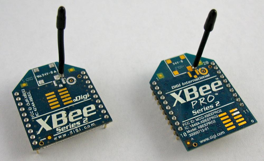
Both the Series 1 and Series 2 radios are available in two different transmission powers, regular and PRO (see Figure 1-1). The regular version is called simply an XBee. The XBee-PRO radio has more power and is larger and more expensive.
The regular version is a slightly less expensive way to get started. For now, we won’t worry about distinguishing between the regular and PRO radios because they are configured in the same way.
Antennas
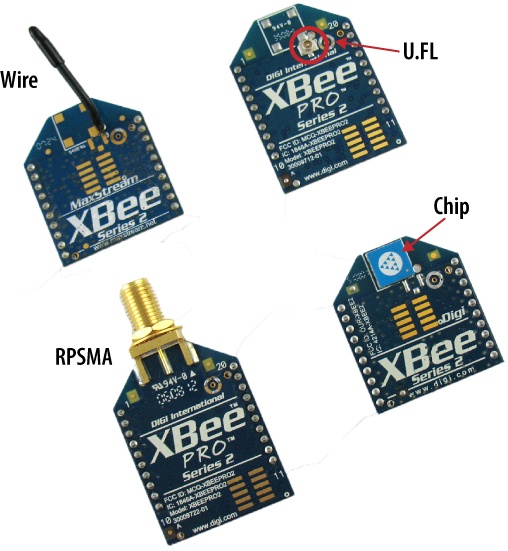
Radios need antennas to transmit and receive signals. There’s more than one way to build an antenna, each with advantages and disadvantages. You probably won’t be surprised to learn that Digi decided to offer plenty of choices. Here are the kinds of antenna options currently available (see Figure 1-2):
- Whip or wire antenna
This is just what it sounds like—a single piece of wire sticking up from the body of the radio. In most cases, the wire antenna is just what you need. It’s simple and offers omnidirectional radiation, meaning the maximum transmission distance is pretty much the same in all directions when its wire is straight and perpendicular to the module.
- Chip antenna
Again, this is pretty much what it sounds like. The chip antenna is a flat ceramic chip that’s flush with the body of the XBee. That makes it smaller and sturdier, but those advantages come at a price. Chip antennas have a cardioid (heart-shaped) radiation pattern, meaning that the signal is attenuated in many directions. However, if you’re making a device where mechanical stress to the wire antenna might break it, or you need to put the radio in a very small space, then the chip antenna may be your best bet. Chip antennas are often the right choice for anything wearable.
- PCB antenna
Introduced with the XBee-PRO S2B, the PCB antenna is printed directly on the circuit board of the XBee. It is composed of a series of conducting traces laid out in a fractal pattern. The PCB antenna offers many of the same advantages (and disadvantages) as the chip antenna with a much lower cost to manufacture.
- U.FL connector
This is the smaller of the two types of external antenna connectors. More often than not, an external antenna is not needed: it is an additional expense if a simple wire antenna will do. However, when your radio is going to live on the inside of a metal box then the antenna will need to live on the outside. That way the signal is not attenuated by the enclosure. Also, it is sometimes advantageous to orient an external antenna differently than the XBee itself to or use a special-purpose antenna with a specific radiation pattern, such as a high-gain antenna that passes signals in a single direction over a broader distance. The U.FL connector is small, somewhat fragile, and almost always used with a short connecting cable that carries the signal from a remotely mounted antenna.
- RPSMA connector
The RPSMA connector is just a different type of socket from the U.FL connector. It’s bigger and bulkier, but you can use it with an external antenna, mounted directly to the XBee without a connecting cable. For most introductory projects, you’re still best off with the simple wire antenna that is smaller, cheaper, and usually just as good.
To keep it simple you can get started by purchasing two (or more) of the regular Series 2 XBees with wire antennas. Don’t buy just one! You’ll be as disappointed as a kid at Christmas who finds a single walkie-talkie under the tree. Here’s the model number to get you started: XB24-Z7WIT-004. At the time of this writing, this module cost about $25.
Note
If you need a chip antenna, the part number is XB24-Z7CIT-004. If you require a PRO high-power radio, use part number XBP24BZ7WIT-004.
Vendors
Now that you know what you want to buy, you also need to decide where to buy it. XBee radios are available directly from Digi, and also from many online resellers. This is a list of vendors that typically stock XBees, as well as many other nifty electronic components you may need for your projects:
- Digi International
Digi manufactures and sells all varieties of XBee radios and some interesting XBee starter kits, generally at the suggested retail price. They don’t sell any other electronic components.
- Maker SHED
MAKE: magazine (which is published by O’Reilly, the publisher of this book) offers a kit specifically designed for this book, via their in-house maker emporium. The kit includes many of the parts you’ll need, including appropriate XBees.
- SparkFun Electronics
SparkFun carries a rapidly growing array of prototyping supplies designed specifically for DIY electronics enthusiasts, including most of the XBee modules. You’ll find documentation links for each part, as well as handy tutorials for using many of the components.
- DigiKey
DigiKey offers a dizzying array of electronic components for the professional electrical-engineering market. It’s normal to feel overwhelmed at first by the selection of about half a million different parts, but it’s worth learning the ropes because you’ll be able to buy almost anything you want and receive it the next day. The entire XBee line is usually represented at DigiKey (which has no relationship at all to Digi International).
Buying an Adapter
You’ll be using a computer to configure your XBee and to send and receive data directly from your desktop or laptop. The XBee is made to be soldered directly into a printed circuit board, so you’ll need an adapter to connect it to your computer’s USB port. If you need to connect to an older 9-pin or 25-pin serial port instead, check the Appendix A for other options.
There are several different adapters available, along with a few handy hacks if you want to avoid buying one or if you get caught without one.
Digi Evaluation Board
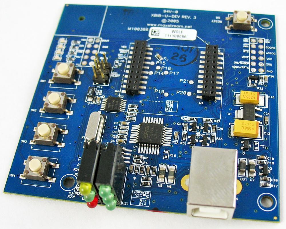
If you buy a complete drop-in networking starter kit from Digi, such as their iDigi Professional Development Kit ZB (part no. XK-Z11-PD), it will include an evaluation board with a power supply, a USB connector, and some handy buttons and lights (Digi part no. XBIB-U). The kits are a good value if you need everything they include. However, if you only want some radios and an adapter, other approaches are more cost-effective. Also, the Digi evaluation board is substantially larger than most third-party adapters, making it somewhat cumbersome to carry around. At the time of this writing, the development kit was available for $300, though occasional promotions have brought it down to $150. (See Figure 1-3.)
USB Adapters
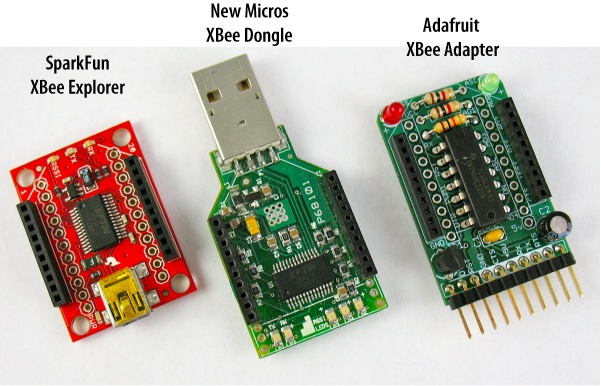
Several different XBee USB adapters are available from third-party manufacturers (see Figure 1-4):
Note
Almost all XBee USB adapters require drivers from FTDI (http://www.ftdichip.com/Drivers/VCP.htm). Be sure to install these before using your adapter.
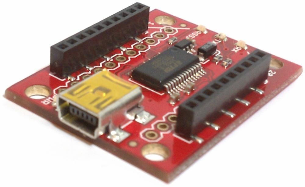
- SparkFun XBee Explorer
The Explorer is a very popular adapter that uses a fairly standard USB A to mini-B cable to connect with your computer. We’ll be using it in most of the examples in this book. The cable is sold separately, but before you buy, check to see if you already have one. Many digital cameras come with this type of cable. Be aware that if you add male headers to use it in a breadboard, the pin order will not be the same as on the XBee. Check the data sheet carefully if you are using the Explorer with a breadboard setup. (About $25; http://www.sparkfun.com/commerce/product_info.php?products_id=8687.)
- Adafruit XBee Adapter Kit
This is an inexpensive board that you’ll need to solder together yourself. It also must be used with a special USB cable called the FTDI USB TTL-232, which can attach to its pin headers. The cable can be used with certain Arduino-type boards as well. Male headers can be added so that this adapter can be used in a breadboard. (About $10; http://www.adafruit.com/index.php?main_page=product_info&cPath=29&products_id=126. Cable about $20; http://www.adafruit.com/index.php?main_page=product_info&cPath=29&products_id=70.)
- New Micros XBee Dongle
One of the smallest adapters, it needs no external cable. The Dongle does not provide any access to the radio beyond USB. Also, because it has no cable, its shape sometimes interferes with other cables or the computer casing. On the other hand, it’s a very small all-in-one device that’s easy to carry in a pocket. It’s terrific for use on the go. (About $39; http://www.newmicros.com/cgi-bin/store/order.cgi?form=prod_detail&part=USB-XBEE-DONGLE-CARRIER.)
- Gravitech XBee to USB Adapter
Like the Explorer, this is another simple adapter board that uses the USB A to mini-B cable (not included). This one also has standard breadboard pinouts. (About $28; http://store.gravitech.us/xbtousbad.html.)
Breakout Boards
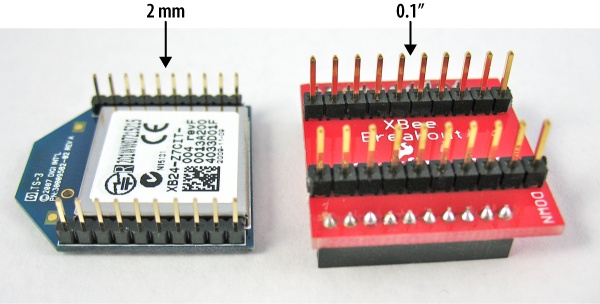
All XBee radios have 20 connection pins, each spaced 2 mm apart. The tight spacing of the pins helps to keep the radios very small, but doesn’t allow them to fit into a solderless breadboard. Luckily, this is a very easy problem to solve. Simple XBee breakout boards that adapt to 0.1″ breadboard spacing (see Figure 1-7) are available from:
You will generally need to solder 2 mm female pin headers to one side of these breakout boards, and regular 0.1-inch male headers to the other side.
Note that the XBee Explorer (Figure 1-8), Adafruit XBee Adapter Kit, and the MCPros XBee Simple Board each have mounting holes for 0.1-inch male headers. Solder a set of male header pins into them to adapt these for breadboard use.
Arduino Board Adapter Hack
The Arduino microcontroller board we’ll be using in Chapter 4 can be modified to function as an adapter for XBee radios. This is a useful hack if you don’t want to buy an adapter—or anytime you find yourself caught without your regular XBee adapter setup. You’ll still need a breakout board, however.
Warning
This hack allows you to connect to the XBee from a terminal program (described later in this chapter). It lets you use some features of X-CTU (also described later), but it does not support firmware upgrades. For that, you should use a proper XBee adapter.
Here’s what you’ll need:
XBee radio (see Buying an XBee Radio)
XBee breakout board (see Breakout Boards)
Arduino microcontroller board with USB connection (Uno or similar) (SFE DEV-09950, AF 50)
USB A-to-B-type cable (AF 62, DK 88732-9002, SFE CAB-00512)
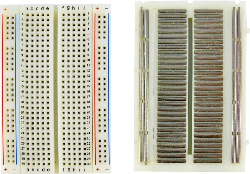
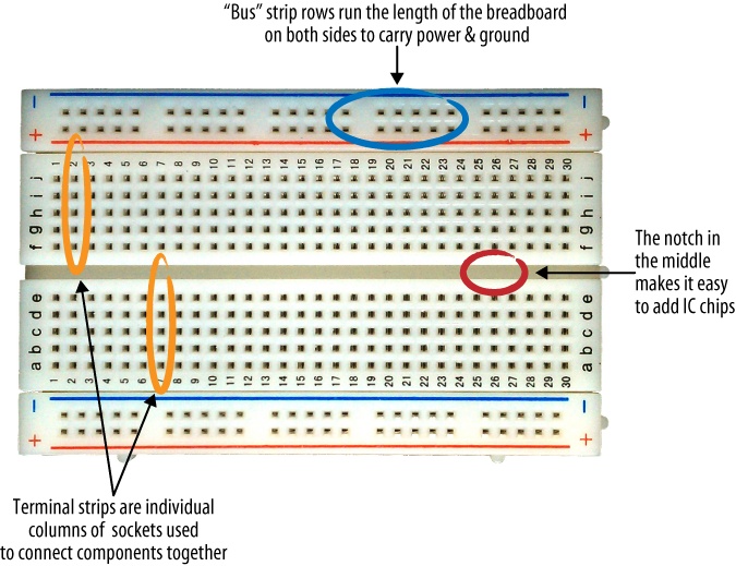
Solderless breadboard (AF 64, DK 438-1045-ND, SFE PRT-09567)
Hookup wire (22 gauge or similar, different colors) or jumper wire kit (AF 153, DK 923351-ND, SFE PRT-00124)
Wire strippers (AF 147, DK PAL70057-ND, SFE TOL-08696)
IC extractor (DK K374-ND, RS 276-1581) or small flat-blade screwdriver (SFE TOL-09146)
Note
These part numbers are prefaced with abbreviations for the suppliers: DK, DigiKey; SFE, SparkFun Electronics; AF, Adafruit; RS, Radio Shack.
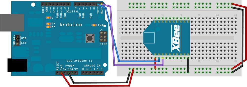
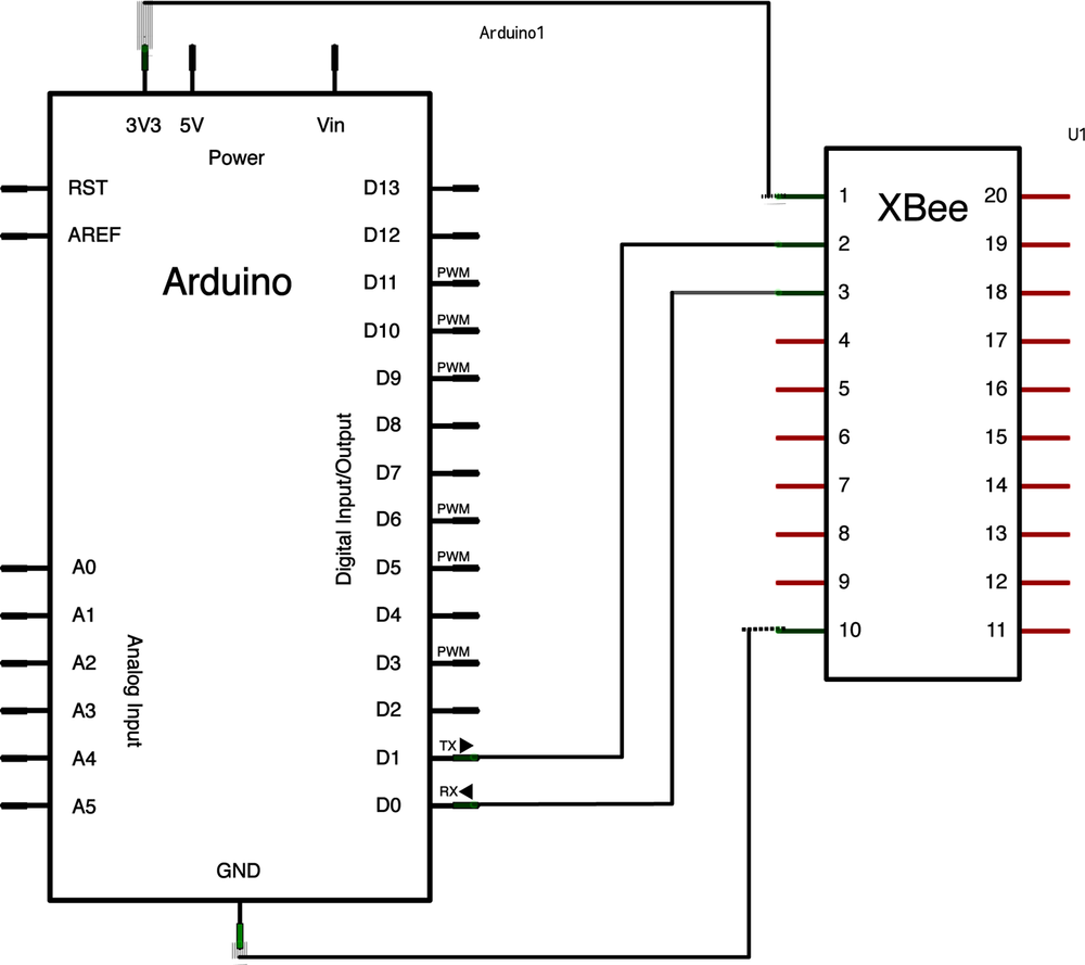
Insert the XBee into the breakout board, then mount the breakout board in the breadboard so that one set of legs is on each side of the breadboard’s center channel. Cut four lengths of wire or select some precut jumper wires long enough to reach from the Arduino to the XBee. Use red, black, and two other colors of wire if you have them. Figure 1-9 shows the Arduino adapter hack breadboard layout, while Figure 1-10 shows the schematic:
Make sure that the Arduino is unplugged from the USB and disconnected from any other external power supply before setting up your wiring.
Carefully remove the ATMEGA chip from the Arduino, using an integrated circuit (IC) extractor or a small flat-blade screwdriver (when you replace it later, be sure the notch at one end of the chip is aligned with the notch in the socket). Or, if you don’t want to pull the chip, program the Arduino with the following null code, which prevents the Arduino chip’s bootloader from responding accidentally:
void setup() {
}
void loop() {
}
Connect a (red) wire from the 3.3 V socket on the Arduino so that it mates with the XBee’s pin 1, the 3.3 V input pin in the upper-left corner of the XBee.
Next, connect a (black) wire from either GND socket on the Arduino so that it mates with pin 10 on the XBee in its lower-left corner.
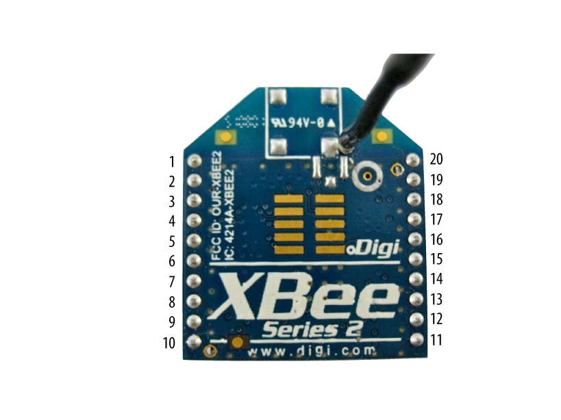
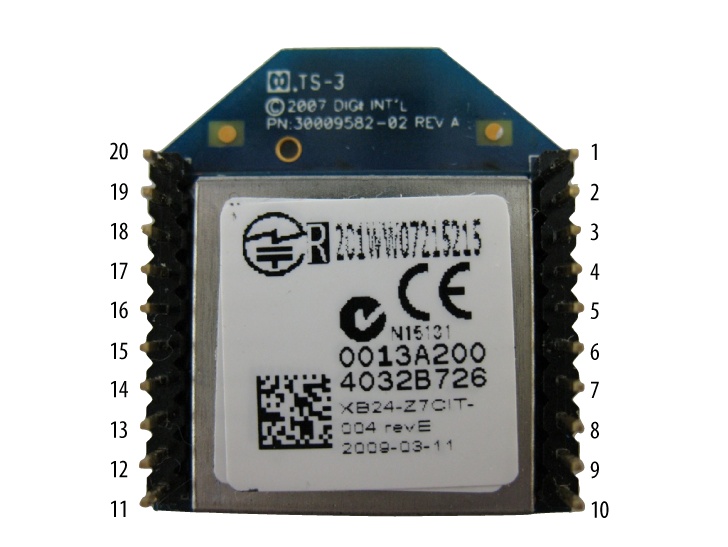
Now wire up a connection from the TX pin (pin 1) on the Arduino to pin 2, the TX/DOUT pin on the XBee. See Table 1-2 and Figures 1-11 and 1-12 for a full list of the XBee’s hardware pins and their functions.
Finally, wire a connection from the RX pin (pin 0) on the Arduino to pin 3, the RX/DIN pin on the XBee.
Check all your connections. It is very important that you supply only 3.3 V power to your radio.
Warning
XBee radios will not work with voltages larger than 3.3. Giving them more than 7 volts will burn them out. When in doubt, remove the radio from your project and confirm the voltage with a multimeter (AF 71, DK BK117B-ND, SFE TOL-09141) before proceeding.
When you’re done with the hack, set it aside for now. You won’t need to power up this circuit until you get to Configuring XBee in Chapter 2.
Note
If you already have an Arduino Mini, you can use the same USB adapter you use for uploading code to the Arduino Mini as a connector for an XBee on a breakout board. For this adapter, wire RX to RX on the XBee and TX to TX on the XBee (http://www.makershed.com/ProductDetails.asp?ProductCode=MKSP3).
What Are All Those Pins?
Pin # | Name(s) | Description |
1 | 3.3 V power supply | |
2 | Data Out (TX) | |
3 | Data In (RX) | |
4 | Digital I/O 12 | |
5 | Module reset (asserted low by bringing pin to ground) | |
6 | Pulse-width modulation analog output 0, Received Signal Strength Indicator, Digital I/O 10 | |
7 | DIO11 | Digital I/O 11 |
8 | Reserved | Do not connect |
9 | Data Terminal Ready (hardware handshaking signal), Pin Sleep Control (asserted low), Digital I/O 8 | |
10 | Ground | |
11 | DIO4 | Digital I/O 4 |
12 | Clear to Send (hardware handshaking), Digital I/O 7 | |
13 | Sleep indicator (off when module is sleeping) | |
14 | Not used in Series 2 | |
15 | Association indicator: blinks if module is associated with a network, steady if not; Digital I/O 5 | |
16 | Request to Send (hardware handshaking), Digital I/O 6 | |
17 | Analog Input 3, Digital I/O 3 | |
18 | AD2/DIO2 | Analog Input 2, Digital I/O 2 |
19 | AD1/DIO1 | Analog Input 1, Digital I/O 1 |
20 |
Choosing a Terminal Program
Each XBee radio has a tiny computer on board. This internal microcontroller runs a program, also known as firmware, that performs all its addressing, communication, security, and utility functions. You can configure this firmware with different settings that define things like its local address, which type of security is enforced, who it should send messages to, and how it should read sensors connected to its local input pins.
To change or upgrade the firmware, we will use a program called X-CTU that you can download from the Digi website. On the upside, this program is totally free. On the downside, it runs only on Windows. Don’t worry if you have limited access to Windows, though. Chances are you’ll only need X-CTU initially, to load the proper firmware onto your XBee radio. Going forward, you can use serial terminal programs on Macintosh, Linux, or Windows to change many of the settings you’ll be working with on a day-to-day basis. Let’s take a look at some of these programs and how they operate.
Firmware Update Software
There is only one option for updating the low-level firmware on XBee radios: Digi’s configuration tool, which is available for free.
X-CTU
The X-CTU program is the official configuration program for XBee radios. As noted, X-CTU is available only for the Microsoft Windows operating system. If you have access to a native Windows computer, a Macintosh running Windows under Boot Camp or Parallels, or a Linux computer running the WINE Windows emulator (see X-CTU in Linux in Chapter 2), you’re all set. Luckily X-CTU is required only for updating firmware, which is a relatively infrequent task. It does have a number of other handy features, though, including fully commented setup commands, range tests, and easier access to the API features we’ll be examining in Chapter 5.
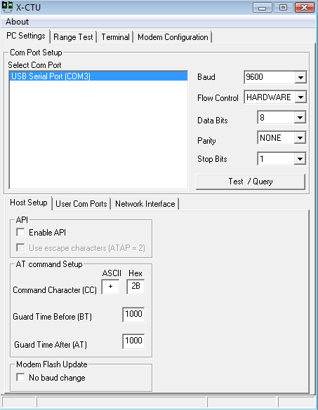
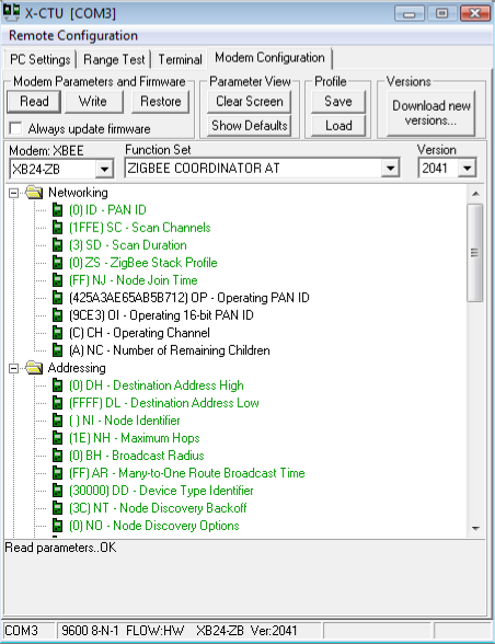
To use X-CTU, plug your XBee radio into a USB adapter and plug that adapter into one of your computer’s USB ports. Next, launch the X-CTU program. It should show your USB connection as one of the available ports, similar to what you see in Figure 1-13. Select the appropriate port and then click on the Modem Configuration tab to get to a basic configuration screen (Figure 1-14). Clicking on the Read button will generally access the radio’s setup, though this depends upon which firmware is currently loaded. Don’t be concerned if you get an error message instead. We’ll go over the details in the next chapter.
Terminal Software for Configuring Settings
Once you’ve loaded the firmware, you may want to use a different program to communicate with your XBee. It’s very helpful to have some familiarity with one or more serial terminals because you may not always have access to X-CTU when you need it. At a friend’s house, a hacking workshop, a public demo, or in the midst of a Maker Faire, you might need to check something or change a setting on a non-Windows computer. Or you may run into a Windows machine where you don’t have the rights to download and install new software. Here’s a host of different options that can save you in such cases. We’ll talk about how to set them up and use them in the next chapter.
CoolTerm
CoolTerm is a terrific open source serial terminal program created by Roger Meier that runs well on both Windows and Macintosh. It’s a relatively simple program that’s perfect for most basic tasks you need to perform with XBee radios. CoolTerm is free. Consider making a small donation to show your appreciation and encourage continued support for the program (http://freeware.the-meiers.org).
HyperTerminal
Windows XP and older Windows versions come with a serial terminal program called HyperTerminal. If you are using Windows Vista or Windows 7, HyperTerminal may still be available as a free demo, or for purchase from http://www.hilgraeve.com/hyperterminal.html.
Tera Term
Tera Term is a free, open source Windows program that performs a wide variety of terminal functions, including acting as a serial terminal. Those using Vista or Windows 7 will appreciate having a free option, since HyperTerminal is no longer bundled with Windows and must be purchased separately. This is the Windows software we’ll use to demonstrate serial terminal use (http://ttssh2.sourceforge.jp/).
ZTerm
An old favorite terminal program on the Macintosh, ZTerm has been showing its age for quite some time. It was designed in 1992 and was last updated in 2002. Still, it is widely used and despite its anachronistic features and idiosyncratic design, it’s been stable for almost 20 years. You’ll find some brief setup documentation on my blog, and you can download ZTerm and pay its small shareware fee online (http://homepage.mac.com/dalverson/zterm/).
screen
For Linux users and for those comfortable in the Macintosh
Terminal, there’s a command-line program named screen that allows direct access to serial
ports, including USB devices. On Mac OS X, the command ls dev/tty.* will list the available
ports, returning a list like this:
/dev/tty.Bluetooth-Modem /dev/tty.Bluetooth-PDA-Sync /dev/tty.usb-A410032.
On Linux, try ls
dev/ttyUSB*. Your serial port will probably be something
like /dev/ttyUSB0.
Once you know what your USB port is called, you can invoke the
screen program, using the port
and a data rate of 9600 baud. For example:
screen /dev/tty.usb-A410032 9600
To exit, type Ctrl-A followed by Ctrl-\ and then y to quit.
The picocom program, described in the sidebar A Serial Terminal Program for Linux in Chapter 2, is an alternative to screen and has certain features (such as
local echo) that can be useful for working with XBees.
Summary
Here is a basic shopping list that will work well for this book. Feel free to customize it according to your interests and the projects you have planned:
Three XBee ZBs with wire antenna (Digi: XB24-Z7WIT-004, DK602-1098-ND)
One or two XBee Explorers (SFE: WRL-08687)
One or two USB A to Mini-B cables (SFE: CAB-00598)
X-CTU for Windows (free)
CoolTerm (free)
Now that you know what to get, go do it! As soon as your components arrive, you will probably be itching to use them. The next chapter will help you transform your box of parts into a working ZigBee network. You’ll be chatting wirelessly in no time.
Get Building Wireless Sensor Networks now with the O’Reilly learning platform.
O’Reilly members experience books, live events, courses curated by job role, and more from O’Reilly and nearly 200 top publishers.
