July 2023
Intermediate to advanced
368 pages
15h 38m
English
Note: Figure D.1 in this appendix provides an N2 diagram (see Section 3.2.4) of the typical inputs and outputs that appear in the IPO diagrams in this handbook. The off-diagonal squares represent the typical inputs/outputs shared by the processes that intersect at a given square. Outputs flow horizontally, inputs flow vertically, and the diagram can be read in a clockwise fashion. These typical inputs and outputs represent “a” way that the SE processes can be performed, but not necessarily “the” way that they must be performed. The absence of a relationship between any two processes does not preclude tailoring to create a relationship. Definitions of the typical inputs and outputs on the IPO diagrams can be found in Appendix E.
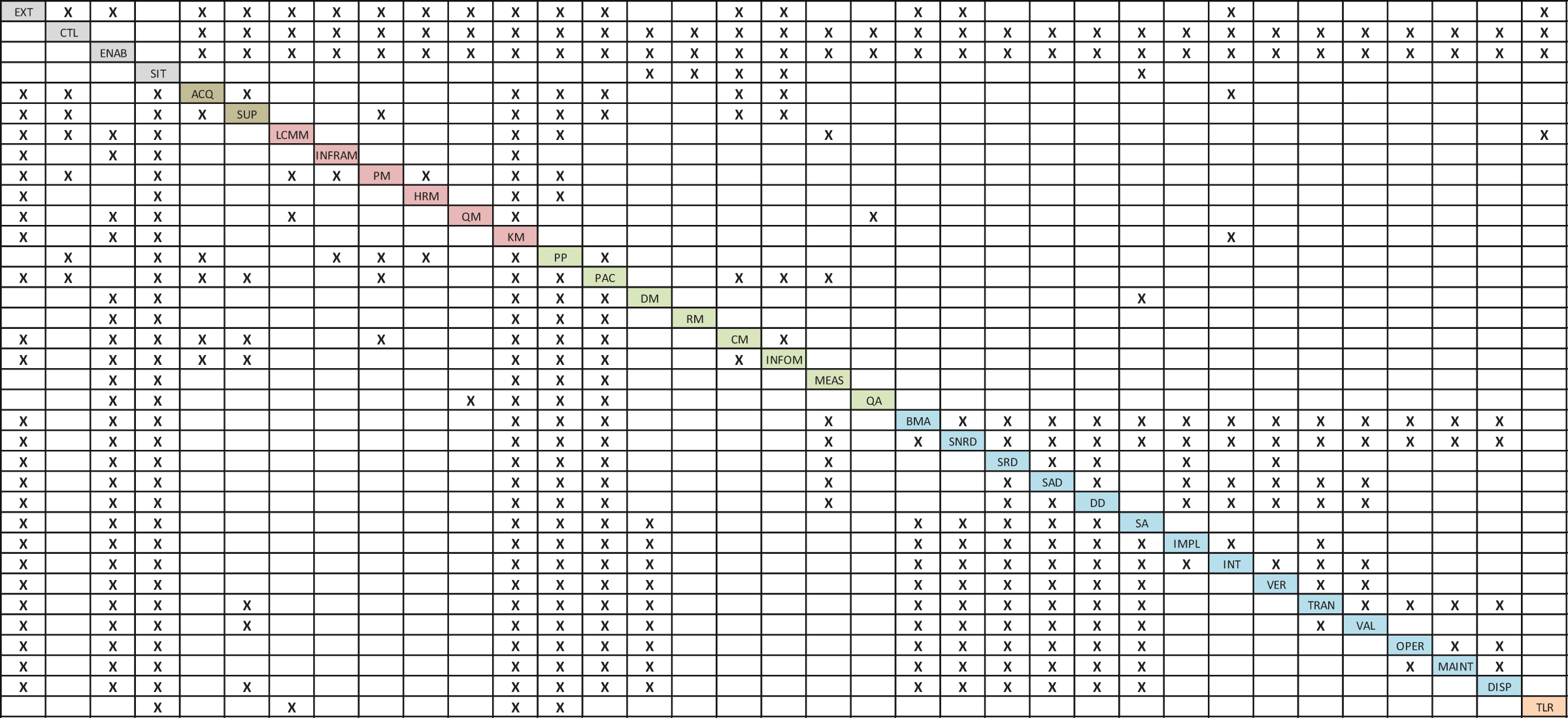
FIGURE D.1 Input/output relationships between the various SE processes. INCOSE SEH original figure created by Shortell, Walden, and Yip. Usage per the INCOSE Notices pages. All other rights reserved.
The system life cycle processes are placed on the diagonal, abbreviated as follows:
| Abbreviation | Life Cycle Process | Handbook Section |
|---|---|---|
| ACQ | Acquisition | 2.3.2.1 |
| SUP | Supply | 2.3.2.2 |
| LCMM | Life Cycle Model Management | 2.3.3.1 |
| INFRAM | Infrastructure Management | 2.3.3.2 |
| PM | Portfolio Management | 2.3.3.3 |
| HRM | Human Resource Management | 2.3.3.4 |
| QM | Quality Management | 2.3.3.5 |
| KM | Knowledge Management |
Read now
Unlock full access


