5
TFT Substrate for OLED Driving
Thin-film transistor technologies for active-matrix driving are discussed in this chapter.
5.1 TFT STRUCTURE
Figure 5.1 shows structural differences between polysilicon (polycrystalline silicon) and amorphous silicon (sometimes abbreviated as a-Si or α-Si).
Figure 5.1 Differences between (a) polysilicon (inside grain) and (b) (hydrogenated) amorphous silicon.
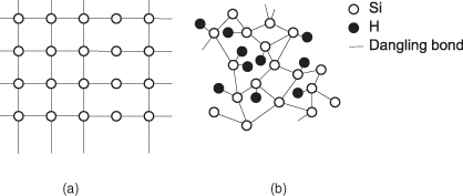
As shown in the figure, amorphous silicon has an irregular structure, so the potential energy is irregularly distributed. Therefore, the moving charge is scattered and mobility is low. The binding state fluctuates as a result of trapping and detrapping, so TFT characteristics change over time. On the other hand, polysilicon inside a grain has a cubic crystalline structure similar to that of single-crystal silicon, where the charges move within a periodical potential in the same way as in a single crystal, so the mobility is very high and stable.
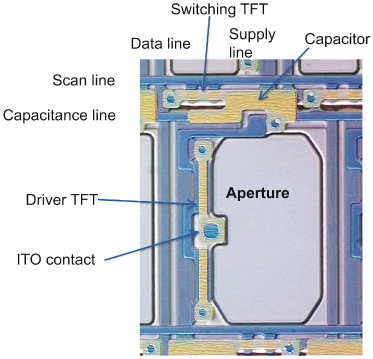
Figure 5.2 shows a TFT substrate used in an actual active-matrix OLED display product. It is very similar to the LCD display TFT backplane except for the existence of a driver TFT in the OLED backplane.
Figure 5.2 An example of a polysilicon-driven OLED display panel.
There are two basic types of TFT structure, according to the electrode configuration: ...
Get OLED Display Fundamentals and Applications now with the O’Reilly learning platform.
O’Reilly members experience books, live events, courses curated by job role, and more from O’Reilly and nearly 200 top publishers.

