Chapter 11. PNG Options and Extensions
In addition to the core chunk types described thus far, the Portable Network Graphics format supports a whole host of optional chunks for various purposes, from text annotations to conversion information. These are described in the following sections, very roughly in order of importance to the average user.
Background Color (bKGD)
- Status: PNG Specification
- Location: After PLTE, before first IDAT
- Multiple: no
In some applications, notably web browsers, there is a natural background surrounding all images, against which images can be composited with transparency information. But standalone image viewers typically have no preferred background color or pattern and usually default to black, which may not be appropriate for some images. PNG therefore supports the concept of a preferred background color that can be used if nothing better is available.
The bKGD chunk is used for this purpose. Just as with the transparency chunk, tRNS (see Chapter 8, “PNG Basics”), the format of bKGD depends on the image type. For palette-based images it contains a single byte, whose value is the palette index of the color to be used for the background. For grayscale images, with or without alpha, the chunk contains a 2-byte, unscaled gray value, just as with tRNS--that is, the maximum allowed value is 2bit depth-1, even though it is stored as a 16-bit integer. And for truecolor images, the background chunk is exactly analogous to the grayscale version except that it contains three 16-bit, unscaled values representing the red, green, and blue components of the background color. There is no requirement in any of the three cases that the background color be present in the actual image data.
Note that colored backgrounds are not supported in grayscale images; while this is certainly a restriction, it appears not to be a particularly serious one, to judge by the lack of public comment to date. Note also that the background color should always be considered fully opaque, even if it happens to match a color marked by the tRNS chunk as partly or fully transparent.
Timestamp (tIME)
- Status: PNG Specification
- Location: anywhere [85]
- Multiple: no
The timestamp chunk provides a way for the author (or image-editing software) to record the time and date the image was last modified. The chunk contains 7 bytes of data, shown in Table 11-1.
| Field | Length and Valid Range |
| Year | 2 bytes (0-65,535) |
| Month | 1 byte (1-12) |
| Day | 1 byte (1-31) |
| Hour | 1 byte (0-23) |
| Minute | 1 byte(0-59) |
| Second | 1 byte (0-60) |
As this book is being written before the Third Millennium begins, the first thing to notice is that PNG is not merely Y2K-compliant, but also Y2038, Y10K, and pretty much everything else on up through Y65K.[86] In addition, note that the seconds field is permitted to vary between 0 and 60; this allows for leap seconds, of which there have been roughly two dozen since 1972. (There has never been more than one leap second in any given minute, however.)
On a less technical level, why does tIME store the modification time rather than creation time? On the face of it, creation time would seem like a more useful piece of information, and indeed, it is explicitly supported in PNG via the text chunks described later. But whereas modification time is a well-defined quantity--even a computer program can determine whether the image data has been modified--creation time is ambiguous. If a scanned photograph of the Mona Lisa is converted to PNG format, is its creation time the time of image conversion, the time of the original scan, the time the photograph was taken, or even the time the painting was created? The case becomes even muddier if an artist creates a digital work partly based on the scanned image. So creation time is supported via one or more text chunks, which can also describe in precisely what sense the image was created.
Latin-1 Text Annotations (tEXt, zTXt)
- Status: PNG Specification
- Location: anywhere
- Multiple: yes
That brings us to PNG's original text chunks, which are perhaps its most popular nonessential chunks. Regardless of how many words a picture is worth, it is often useful or necessary to add a few more in order to record pertinent information like title and author, store requisite legal notices such as a copyright or disclaimer, or merely to transfer text from one image to another.
PNG supports two types of Latin-1-based text chunks, uncompressed (tEXt) and compressed (zTXt). There is also a new Unicode-based chunk (iTXt) that I'll discuss next. For the first two, the format is basically the same: an uncompressed keyword or key phrase, a null (zero) byte, and the actual text. In zTXt the text is compressed; the first byte after the null indicates the compression method, for which only deflate is currently defined (method zero). The remainder is the compressed stream, which for method zero must be in zlib 1.x format, just as for image data. (The zlib 1.x format is described by revision 3.3 of the zlib specification, which is available from http://www.zlib.org/zlibdocs.html/.)
Both keyword and raw text should be encoded with the Latin-1 (ISO/IEC 8859-1) character set; neither may contain null bytes. Since the keyword is intended to be recognizable by both humans and computer programs, additional restrictions are placed on it: it may not contain leading, trailing, or consecutive spaces, and it is restricted to characters in the range 32-126 and 161-255 (which, in particular, rules out both control characters and the nonbreaking space, decimal value 160). The only other restriction on the main text of the chunk is that newlines should be in Unix format, i.e., represented by a single line-feed character (decimal value 10).
I mentioned in Chapter 7, “History of the Portable Network Graphics Format”, that the Unicode UTF-8 character set was one of the items in the design of PNG that was voted down. In retrospect this was, perhaps, a lamentable decision; it was finally addressed early in 1999 with the iTXt chunk. But at the time, UTF-8 was very new and had not been extensively tested in the field. In particular, it had little or no operating-system support and no support in standard programming libraries, either for encoding and decoding or for the translation and display of UTF-8 characters in the native character set(s) of existing systems. Since PNG's design goals included both the use of well-tested technologies and the avoidance of undue burdens on developers of PNG applications, support for UTF-8 was dropped in favor of the more familiar Latin-1 character set.
The following list summarizes all of the keywords that are either included in the specification itself or officially registered as extensions to the spec:
Author
The name of the author of the image. If the original image were a painting or other nonelectronic medium, both the original artist and the person who scanned the image might be listed.
Title
A one-line title or caption. Longer captions should generally use the Description keyword, but see the end of this section for an unofficial alternative.
Description
A longer description of or caption for the image, perhaps including details about the tools and settings used; the name, age, and/or location of the subject matter; or the mood the artist was trying to convey. See also the Software and Source keywords.
Creation Time
The time the image was created, in whatever sense is most appropriate. The recommended format is that prescribed by Internet RFC 822 (Section 5), as amended by RFC 1123 (Section 5.2.14); specifically:
day month year hour:minute timezone
where day is either one or two digits; month is a three-letter English abbreviation such as Jun; year is two or four digits (though the latter is strongly recommended); hour and minute are two digits each; and timezone is either a three-letter abbreviation (e.g., PST for Pacific Standard Time), or a one -letter U.S. military designation, or a four-digit number with a leading positive or negative sign indicating the hour:minute offset from Coordinated Universal Time (e.g., -0800 for Pacific Standard Time, which is eight hours and zero minutes earlier than UTC). In addition, the entire string may optionally be preceded by a weekday field, where weekday is a three-letter English abbreviation (e.g., Fri). A colon and two-digit seconds field may also be appended to the time (that is, hour:minute:second). Note that this is merely a recommendation; strings such as “circa 1492” are allowed, as is explanatory text following an RFC-style date string.
Copyright
The legal copyright notice for the image. For example, “Copyright 1999 by Greg Roelofs. This image may be freely used and distributed provided that it is not modified in any way and that this notice remains intact.”
Disclaimer
A legal disclaimer notice for the image. This might include a company's standard boilerplate on all copyrighted works; in particular, it might be lengthy enough to store in a compressed (zTXt) chunk, while the copyright notice remains uncompressed.
Warning
A warning about the content or effects of the image. For example, certain types of popular material may not be suitable for minors, or a random-dot stereogram (“Magic Eye” 3D image) may induce headaches in some people.
Software
The name and possibly the version of the software used to create the image. This is most often generated automatically, but it need not be. More than one software application may be listed.
Source
Comment
In addition to these official keywords, one of the technical reviewers of this book and I have been known to make use of a few unofficial keywords. The Caption keyword is used to provide a brief description of an image that is more specifically tailored for use as a publishable caption than the generic Description keyword; it is also generally lengthier than is appropriate for the Title keyword. The E-mail keyword stores the email address of the author in standard Internet format (RFC 822, Section 6, as amended by RFC 1123, Sections 5.2.15 through 5.2.19); for example, roelofs@pobox.com. And the URL keyword is for a standard WWW Uniform Resource Locator (RFC 2068, Section 3.2); for example, http://www.oreilly.com/. If the URL is reasonably self-explanatory, it is recommended that the chunk consist of the single URL and nothing else, but this is not a requirement. Multiple URLs should be separated by newline characters. Note that spaces and other white space (tabs, newlines, and so forth) are considered unsafe by the URL standard and therefore must be escaped within a conforming URL. For example, a space character must be encoded as %20. This allows easy parsing of optional explanatory text after a URL: the URL ends when the first white space (space, tab, or newline) is encountered.
International Text Annotations (iTXt)
- Status: PNG Extensions [87]
- Location: anywhere
- Multiple: yes
I previously noted that, as of early 1999, PNG was in the midst of joint ISO/IEC standardization. One of the technical issues in the first Committee Draft vote was the lack of support for non-Western languages, specifically in the text chunks. In fact, the PNG Development Group had already discussed a more general text chunk in mid-1998, but its vote was deferred until there was external interest in it. The ISO comments from Japan and the United States clearly fell into the category of external interest, however, so the iTXt was voted on and approved as part of the PNG specification in early February 1999.
The layout of iTXt is a generalization of tEXt and zTXt, as shown in Table 11-2.
| Field | Length and Valid Range |
| Keyword | 1-79 bytes (Latin-1 text) |
| Null separator | 1 byte (0) |
| Compression flag | 1 byte (0, 1) |
| Compression method | 1 byte (0) |
| Language tag | k bytes (ASCII text) |
| Null separator | 1 byte (0) |
| Translated keyword | m bytes (Unicode UTF-8 text) |
| Null separator | 1 byte (0) |
| Text | n bytes (Unicode UTF-8 text) |
The first field is a keyword, with exactly the same restrictions and officially registered values (Author, Description, and so on) as the tEXt and zTXt chunks. Latin-1 (ISO/IEC 8859-1) was chosen so that existing PNG source code could be used without modification to parse and optionally recognize the keyword.
The keyword is followed by a null separator byte and two compression-related bytes. The first indicates whether the main text is compressed (if its value is 1) or not (if it's 0). If the text is compressed, the next byte indicates its compression method, which currently must be zero for the zlib -encoded deflate algorithm. The two bytes could have been combined, but for historical reasons relating to the method byte in IHDR, the split approach was favored.
After the compression bytes is an optional case-insensitive field indicating the (human) language used in the remaining two text fields. This is necessary not only to render Unicode text properly but also to allow decoders to distinguish between multiple iTXt chunks, which may consist of the same text in different languages--but possibly identical keywords. Unlike both the keyword and the main text, the language tag is plain ASCII text (specifically, the “invariant” ASCII subset of ISO 646, which is itself a subset of both Latin-1 and Unicode UTF-8) conforming to Internet Standard RFC 1766. It consists of hyphen-separated “words” of between one and eight characters each, where the first word is either a two-letter ISO language code (ISO 639), the letter i for tags registered by the Internet Assigned Numbers Authority (IANA) [88] or the letter x for private tags. The second “word” is interpreted as an ISO 3166 country code if it is exactly two characters long or as an IANA-registered code if it is between three and eight characters. Subsequent “words” may be anything, as long as they conform to the general rules. Examples of language tags include cn (Chinese), en-us (American English), no-bok (Norwegian bokmål or “book language”), i-navajo (Navajo), and x-klingon (Klingon, from the fictional Star Trek universe).
A null separator byte terminates the language tag, which is followed by an optional translation of the keyword into the given language. The translated keyword is represented in the UTF-8 encoding of the Unicode character set, which is described in the International Standard ISO/IEC 10646-1, in Internet RFC 2279, and in the Unicode Consortium's reference, The Unicode Standard. Like the primary keyword, it should not contain any newline characters, and it is also followed by a null byte.
The remaining chunk data is the main UTF-8 text, either zlib-compressed or not, according to the compression flag. Since its length can be determined from the chunk length, it is not null-terminated. As with the other two text chunks, newlines should be represented by single line-feed characters (decimal 10), and all other control characters (1-9, 11-31, and 127-159) are discouraged. Note, however, that UTF-8 encodings may contain any of the bytes between 128 and 159; what is discouraged is the set of Unicode characters whose four-byte integer values are 128-159.
That last point is confusing, so perhaps a quick primer on Unicode is in order. The Unicode character set is a mapping between graphic characters (or glyphs) and integers. The simplest representation is called UCS-4 and consists of 4-byte integers, potentially allowing more than two billion characters to be defined. On top of that are a number of possible transformations or encodings of the character set; UTF-8 is one of the more popular ones, encoding 4-byte UCS-4 characters into anywhere from 1 to 8 bytes. All Unicode characters below 128 are encoded as single bytes in UTF-8, and because Unicode characters 1-127 are identical to US-ASCII characters 1-127, the Unicode character set (and UTF-8 in particular) may be thought of as a very large superset of 7-bit ASCII.
Multibyte UTF-8 encodings, on the other hand, are composed entirely of byte values between 128 and 253--which means that bytes 1-9, 11-31, and 127 will never be found in valid UTF-8-encoded text except when representing the characters 1-9, 11-31, and 127. So about half of the control characters that are discouraged in iTXt can be detected simply by checking for those single bytes. The remaining half, characters 128-159, are all encoded with 2-byte sequences that happen to begin with byte value 194: 194 128 through 194 159. The fact that character 128 is discouraged in iTXt's UTF-8 text fields therefore means that the 2-byte encoding 194 128 is discouraged, but the 2-byte encoding 195 128 (A or “Latin capital letter A with grave accent”) is completely acceptable.
Histogram (hIST)
- Status: PNG Specification
- Location: after PLTE, before first IDAT
- Multiple: no
A histogram is nothing more than a frequency-of-occurrence table, and the PNG hIST chunk gives the approximate frequencies of occurrence for pixels of various colors. This information is typically used to decide which colors are the most important if the system is not capable of displaying all of them. Rather than force the decoder to count pixels every time the image is displayed, the histogram places the burden on the encoder, which performs the task only once.
PNG's hIST implementation is tied to the PLTE chunk; if there is no palette, hIST is not allowed. This and one or two other limitations were later recognized and addressed by the sPLT chunk, which we'll discuss next; it is generally favored over hIST, but the latter is smaller, and either may be used. The histogram must contain exactly as many entries as PLTE contains, and each entry is a 16-bit unsigned integer. Since such integers can only represent numbers in the range 0-65,535 and there may be millions of pixels of a given color, the histogram entries often must be scaled and are therefore inexact. The sole exception is the value zero; it is guaranteed to mean that there are no pixels of the corresponding color. A nonzero count that would otherwise be scaled and rounded to zero must instead be rounded up to one.
Truecolor images that include a PLTE chunk as a suggested quantization are a special case. The histogram counts are dependent on the algorithm used by the encoder for quantizing the pixels; if the decoder happens to use a different algorithm, its counts would be different, too. The upshot is that the histogram is particularly approximate in this case. Because truecolor images typically have far more colors than palette entries, the palette entries that do appear should always represent at least one pixel; thus there should be no zero counts in the histogram.
Suggested Palette (sPLT)
- Status: PNG Specification
- Location: before first IDAT
- Multiple: yes
The suggested-palette chunk, sPLT, grew out of an acknowledgment of some limitations in PNG's PLTE, tRNS, and hIST chunks. I have already noted that PLTE is allowed only in palette, RGB, and RGBA images and that hIST is allowed only in images with PLTE; I also noted that tRNS is disallowed in images with alpha channels, which rules out the use of PLTE plus tRNS as a suggested gray/alpha or RGBA palette. sPLT eliminates these restrictions by merging all three of the older chunks into a general-purpose, suggested-RGBA-palette-plus-histogram chunk. In addition, sPLT may contain any number of entries (as long as it doesn't exceed the maximum chunk-size limit of two gigabytes); its entries may have either 8-bit or 16-bit sample depths; and multiple sPLT chunks encoding different suggested quantizations are allowed. A palette-based image may even have an sPLT chunk, perhaps representing a reduced palette for a particular web browser. The format of sPLT, given in Table 11-3, is straightforward.
| Field | Length and Valid Range |
| Palette name | 1-79 bytes (Latin-1 text) |
| Null separator | 1 byte |
| Sample depth | 1 byte (8 or 16) |
| Red value #1 | 1 byte (0-255) or 2 bytes (0-65,535) |
| Green value #1 | 1 byte (0-255) or 2 bytes (0-65,535) |
| Blue value #1 | 1 byte (0-255) or 2 bytes (0-65,535) |
| Alpha value #1 | 1 byte (0-255) or 2 bytes (0-65,535) |
| Relative frequency #1 | 2 bytes (0-65,535) |
| ... | ... |
The number of sPLT entries is implicitly given by the size of the chunk and the sample depth; in the more common case of 8-bit samples, it is obtained by dividing the chunk size, less the length of the palette name and the two subsequent bytes, by six. Entries are required to appear in decreasing order of frequency, but there is no requirement that all of them be different nor that all of them be used by the image. Furthermore, opaque images may include nonopaque sPLT entries, grayscale images may include colored entries, and the sample depth of sPLT is independent of that of the image.
Unlike the suggested practice for PLTE in RGBA images, the red, green, and blue values in sPLT are neither premultiplied by the alpha values nor precomposited against a background color. An encoder would still have to inspect every pixel if it wanted to compute an optimal palette for display of an RGBA image against a patterned background, but sPLT would enable a statistical approach based on the background image's own histogram in that case. And for solid backgrounds, sPLT provides the means to build an optimal palette regardless of the choice of background color.
As with the hIST chunk, frequency values are scaled to the range 0-65,535 and therefore are likely to be approximate. Inflating “important” colors based on the image's subject matter is allowed in sPLT, too. But whereas hIST requires a 0 frequency to correspond exactly to 0 pixels, sPLT allows the 0 value to represent infrequently used or unimportant colors. If all of the frequency values are 0, however, the histogram is undefined.
Note that multiple sPLT chunks are required to have different palette names.
Significant Bits (sBIT)
- Status: PNG Specification
- Location: before PLTE and first IDAT
- Multiple: no
The significant-bits chunk is used to indicate the nature of the source data in cases in which storing it in PNG form required a conversion. For example, gray pixels in medical images are often 12 bits deep, but PNG requires them to be scaled up to 16 bits for portability. Scaling the pixels does not alter the fact that they contain only 12 bits of real information, and the sBIT chunk stores this fact in a PNG file.
As with several other PNG chunks, the format of sBIT depends on the image type. Grayscale images are the simplest; sBIT then contains a single byte indicating the number of significant bits in the source data--in the preceding example, 12. For grayscale images with an alpha channel, sBIT contains 2 bytes, one for the gray channel and one for alpha; RGB images require 3 bytes, and RGBA images require 4. Palette-based images are treated like RGB except that the sBIT information refers to the palette entries, and the palette's effective sample depth is always 8, regardless of how many bits are used to index the palette. Note that the number of significant bits for any given channel must be greater than zero and less than or equal to the sample depth.
Ordinary PNG decoders need not worry about sBIT, but those that wish to recover the original image data can do so by right-shifting each image sample to leave only the number of bits indicated by sBIT. This implies that the scaling procedure used by the PNG encoder must not change the original bits; it can only append low-order bits to each sample.
Physical Pixel Dimensions (pHYs)
- Status: PNG Specification
- Location: before first IDAT
- Multiple: no
The pHYs chunk encodes the absolute or relative dimensions of pixels. For example, an image scanned at 600 dots per inch has pixels with known, absolute sizes--namely, one six-hundredth of an inch in both x and y directions. Alternatively, an image created on a 1280 × 1024 display will have nonsquare pixels, and the relative dimensions of each pixel, also referred to as the aspect ratio, may be stored so the image can be displayed as it was intended to be seen.
The layout of the chunk is shown in Table 11-4.
| Field | Length and Valid Range |
| Pixels per unit, x axis | 4 bytes (0-2,147,483,647) |
| Pixels per unit, y axis | 4 bytes (0-2,147,483,647) |
| Unit specifier | 1 byte (0, 1) |
If the unit specifier byte is 1, the units are meters; if it is 0, the units are unspecified, and only the relative dimensions are known. Currently, no other values are valid. Note that the format of the chunk precludes pixel sizes greater than one meter, which should not be a significant hardship for most applications, but it allows pixels as small as 4.7 Angstroms, which is roughly the size of a single atom.
For the previous scanning example, 600 dpi is equal to 23,622.05 pixels per meter, so both the x and y values would be 23,622, and the unit specifier would be 1. The second example is slightly trickier. First, it is necessary to know that practically all current computer displays have a physical aspect ratio of 4:3, [89] which means the viewable portion of the display (the glass) is three-quarters as high as it is wide. Thus, the horizontal pixels-per-unit in the case of a 1280 × 1024 display is proportional to (1280/4) or 320, while the vertical pixels-per-unit is proportional to (1024/3) or 341.333333. Because we don't have an absolute scale, we are free to multiply these values by a common factor; doing so will preserve some of the precision that would otherwise be lost due to truncation of the decimal part of the second value (the .3333 part). One choice would be a power of 10, such as 1,000; then the stored values would be 320,000 and 341,333, respectively. But in this case, we can do better: we know that the fractional part is simply one-third, so multiplying both values by 3 will preserve the aspect ratio exactly. Thus the chunk would contain the values (3 × 1280/4) or 960, (3 × 1024/3) or 1,024, and 0 for the unit specifier. Values of 15, 16, and 0 would work equally well.
A decoder that encounters a pHYs chunk with different values for the x and y axes has several options. The simplest and least correct approach is to ignore the chunk; most current viewers do this. A better approach is to interpolate the pixels in one of the dimensions; this gives the correct overall appearance but introduces noticeable artifacts--for the preceding example, it involves either duplicating every 15th column stretching the image horizontally, or deleting every 16th row shrinking the image vertically. The best approach is to resample the image, a procedure that amounts to converting the image to a continuous (or analog) representation and then overlaying the desired pixel grid on that. This is, by far, the most expensive approach in terms of CPU usage, but the results are excellent.
Physical Scale (sCAL)
- Status: officially registered (PNG Extensions)
- Location: before first IDAT
- Multiple: no
PNG's sCAL chunk is similar to pHYs, except that instead of measuring the size of the image pixels relative to each other or to an original, physical image, sCAL measures their size relative to the actual subject matter of the image. For example, an astronomical image may span a certain number of radians in each direction, or an aerial photograph of Earth may cover a given number of kilometers.
Table 11-5 shows the format of sCAL; it is quite simple.
| Field | Length and Valid Range |
| Unit specifier | 1 byte (1, 2) |
| Units per pixel, x axis | m bytes (positive floating-point) |
| Null separator | 1 byte (0) |
| Units per pixel, y axis | n bytes (positive floating-point) |
Two units are defined: meters (unit specifier = 1) and radians (unit specifier = 2). The size of a pixel in the given units, both horizontally and vertically, is given by a pair of positive floating-point numbers encoded as ASCII strings and separated by a null byte. The most general form of a floatingpoint string includes an optional leading sign (+ or -), zero or more decimal digits (0-9, the “integer part”), an optional decimal point followed by zero or more decimal digits (the “fractional part”), and an optional e or E followed by an optional sign and one or more digits (the “exponent part”). Either the integer part or the fractional part must contain at least one digit, but everything else may be omitted. Thus, 1 and .1 are valid floating-point numbers, as is +123.4567e-089. Note that the exponent is interpreted as a power of 10 (10−89 in the third example) to be multiplied by the integer and fractional parts; this is the computer version of what is sometimes referred to as scientific notation.
Image Offset (oFFs)
- Status: officially registered (PNG Extensions)
- Location: before first IDAT
- Multiple: no
For images that are available separately but envisioned as part of a greater whole, the image-offset chunk, oFFs, can be used to specify the absolute positioning of each. The most common example is positioning on a printed page, especially in conjunction with the pHYs chunk.
The layout of the chunk is given in Table 11-6.
| Field | Length and Valid Range |
| Image position, x axis | 4 bytes (-2,147,483,647 to +2,147,483,647) |
| Image position, y axis | 4 bytes (-2,147,483,647 to +2,147,483,647) |
| Unit specifier | 1 byte (0, 1) |
Valid units are either pixels (unit specifier = 0) or microns
[90] (unit specifier = 1). The image position is measured from the top and left edges of the page (whether real or virtual); an image that is intended to be partly cut off may have negative offsets.
Pixel Calibration (pCAL)
- Status: officially registered (PNG Extensions)
- Location: after PLTE, before first IDAT
- Multiple: no
The pCAL chunk is currently the only registered scientific-visualization extension to PNG, though it was moved into the regular PNG Extensions document as part of the general PNG spec revision process in October 1998. It is also the most mathematical of any approved chunk. Its purpose is to efficiently encode the relevant conversions between the integer samples in a PNG file and the physical quantity being represented by the image. Two conversions are represented: a linear conversion between the PNG samples and the original samples and a more general conversion from the original samples to the physical values they represent. The first mapping is often the identity mapping (i.e., the original samples are equal to the PNG samples), but it need not be.
The layout of the pCAL chunk is presented in Table 11-7.
| Field | Length and Valid Range |
| Calibration name | 1-79 bytes (Latin-1 text) |
| Null separator | 1 byte |
| Original zero, X0 | 4 bytes (signed integer) |
| Original maximum, X1 | 4 bytes (signed integer) |
| Equation type | 1 byte |
| Number of parameters, N | 1 byte |
| Unit name | n bytes (Latin-1 text) |
| Null separator | 1 byte |
| Parameter 0, P0 | p0 bytes (ASCII floating-point text) |
| Null separator | 1 byte |
| ... | ... |
| Parameter L, PL | PL bytes (ASCII floating-point text) |
| (Note: L = N-1) | |
The unit name is a label, such as kg/(m^3) or Mpc, that applies to the physical quantity represented by the image samples. Dimensionless data may either include a descriptive string (e.g., “fractal iteration count”) or leave the unit field a null string. There are no restrictions on the length of the unit name.
The X0 and X1 parameters encode the linear conversion. For an 8-bit sample depth, the PNG samples range from 0 to 255; more generally, they range from 0 to M, where M = 2bit depth - 1. Most often, X0 will equal 0 and X1 will equal M, indicating that the PNG samples are the same as the original samples. But this need not be the case, and either of X0 or X1 may be positive or negative; the only restriction is that they may not be equal to each other. The conversion is done using integer arithmetic, according to the following equation:
original_sample = (PNG_sample * (X1-X0) + M/2) / M + X0
The inverse mapping is:
PNG_sample = ((original sample - X0) * M + (X1-X0)/2) / (X1-X0)
Note that integer arithmetic here means that fractional values are rounded toward minus infinity, not toward zero; there's no difference for positive values, but for negative values, there is. Also keep in mind that the PNG samples are limited to the range [0,M] regardless of what the inverse mapping might give.
The more general conversion, between original samples and actual physical values, can be represented by one of four possible equation types: linear (type 0), exponential (type 1), exponential with arbitrary base (type 2), or hyperbolic sinusoidal (type 3). The number of parameters required by each is 2, 3, 3, and 4, respectively, and the parameters are stored in the same ASCII floating-point format as described for the sCAL chunk earlier. The equations use floating-point arithmetic, not integer, and are given by:
[0] physical_value = P0 + P1 * original sample/(X1-X0)
[1] physical_value = P0 + P1 * eP2 * original_sample/(X1-X0)
[2] physical_value = P0 + P1 * P2original_sample/(X1-X0)
[3] physical_value = P0 + P1 * sinh(P2*(original_sample - P3)/(X1-X0))
Equation types 1 and 2 are equivalent in the sense that the same types of functions can be represented by either one; both are defined for convenience. For RGB or RGBA image types, the equations are applied to each of the color sample values independently, while for palette images, the equations are applied to the color sample values in the palette, not to the index values.
Equation type 3 may seem odd, but it allows floating-point data to be reduced to integer data in such a way that the resolution of the integer data is roughly proportional to the magnitude of the original floating-point data. That is, for 32-bit original data and 16-bit PNG samples, the resolution near zero is around 10−33, and near ±1031 it is around 1028. To put it another way, the resolution everywhere is about 0.4% (or 1/256) of the magnitude.
Fractal Parameters fRAc)
- Status: officially registered (PNG Extensions)
- Location: anywhere
- Multiple: yes
The fRAc chunk is unique in that it was officially registered as a PNG extension in 1995 but, as of early 1999, still had not actually been specified. Intended to store parameters pertaining to the generation of fractal images, the chunk is clearly useful only to a very specialized set of programs. As a result, its design was left in the hands of experts--specifically, the authors of Fractint, which is one of the most general fractal programs ever written and probably the most popular. But for technical reasons relating to Fractint's 16-bit origins, PNG support was not added as planned, so design of the fRAc chunk was deferred pending a rewrite of the program as a 32-bit application.
GIF Conversion Info (gIFg, gIFx)
- Status: officially registered (PNG Extensions)
- Location: anywhere
- Multiple: yes
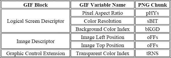
Since PNG originated as an intended replacement for GIF, one requirement for the new format was to be able to store all possible GIF information in one form or another. Part of that requirement is addressed by chunks we've already described. Within GIF's Logical Screen Descriptor (the global header that immediately follows the GIF signature bytes), the Pixel Aspect Ratio, Color Resolution, and Background Color Index fields map to pHYs, sBIT, and bKGD, respectively. Note that Background Color Index only applies if there is a Global Color Table, however. Within the Image Descriptor, the Image Left Position and Image Top Position fields map to oFFs. And within the Graphic Control Extension, the Transparent Color Index maps to tRNS. This is summarized in Table 11-8.
Table 11-8. Correspondence Between GIF Fields and Standard PNG Chunks
The remainder of the requirement that PNG be able to store all GIF information is addressed by two of PNG's three GIF extension chunks. Both correspond directly to GIF89a extensions: the Graphic Control Extension (gIFg) and the Application Extension (gIFx). The third chunk, gIFt, turns out to be an unintended special case; it is discussed separately later.
GIF's Graphic Control Extension is most commonly used to indicate transparency, for which it corresponds most closely to PNG's tRNS chunk. But it is also used in multi-image GIFs to provide timing and compositing information. Although this is more properly the realm of MNG, PNG's multiimage cousin (which I'll discuss in Chapter 12, “Multiple-Image Network Graphics”, PNG also supports the conversion of a multi-image GIF into several single-image PNGs. The gIFg chunk is used to encode the nontransparency information in the GIF extension block so that lossless conversion back to an animated GIF is possible.
The gIFg chunk, shown in Table 11-9, contains only three fields.
| Field | Length and Valid Range |
| Disposal method | 1 byte (0-3) |
| User input | 1 byte (0, 1) |
| Delay time | 2 bytes (0-65,535) |
The interpretation and value of each field are identical to those in part 23 of the GIF89a Specification, with the exception that the 2-byte delay time is stored in big-endian order (most significant byte first) in gIFg, whereas GIF integers are stored in little-endian format. PNG decoders may treat the delay time (measured in hundredths of a second) as the maximum amount of time to display the image before going on to the next one, if any, but it is likely that most decoders will ignore the chunk entirely.
GIF's Application Extension is simply a way for an application to include its own information in the image; it corresponds exactly to a private chunk in a PNG image. The format is given in Table 11-10.
| Field | Length and Valid Range |
| Application identifier | 8 bytes (printable ASCII characters) |
| Authentication code | 3 bytes |
| Application data | n bytes |
The contents of gIFx are a direct transcription of the GIF data, with the sole exception that any GIF sub-blocks are deblocked into a flat stream.
GIF Plain Text (gIFt)
- Status: officially deprecated (PNG Extensions)
- Location: anywhere
- Multiple: yes
GIF's Plain Text Extension is a way to define an image composed entirely of text without actually storing the text as a bitmapped image. It defines a rectangular grid of character cells into which text characters of the specified foreground and background colors are placed, starting from the upper left and proceeding left to right and top to bottom; the decoder chooses the font that is the closest match to the specified size.
A casual reading of the GIF specification might suggest that the Plain Text Extension defines a method for cheaply overlaying fixed-width text on top of ordinary pixel data--and, indeed, that was probably the primary motivation behind the extension. But a more careful inspection reveals that the Plain Text Extension is treated as a separate subimage within the GIF stream, on equal terms with any block of bitmap data. It may, in fact, be the only graphic rendering block within the stream. And since PNG images are required to include bitmap data (i.e., IDAT chunks), allowing GIF Plain Text information to be included is perilously close to sanctioning multi-image PNGs. Largely because of this, the gIFt chunk was officially deprecated in October 1998. It is still allowed for backward compatibility (the horses have already left the barn, so to speak), but the current recommendation is that all decoders ignore the chunk and that encoders not write it in the first place. In fact, it is quite possible that no encoder or decoder ever did support gIFt; the Plain Text Extension was rarely used even in GIF's heyday, and even gif2png (see Chapter 5, “Applications: Image Converters”) never supported it.
In any case, the format of the gIFt chunk is as shown in Table 11-11.
| Field | Length and Valid Range |
| Text grid left position, pixels | 4 bytes (0-2,147,483,647) |
| Text grid top position, pixels | 4 bytes (0-2,147,483,647) |
| Text grid width, pixels | 4 bytes (0-2,147,483,647) |
| Text grid height, pixels | 4 bytes (0-2,147,483,647) |
| Character cell width, pixels | 1 byte (0-255) |
| Character cell height, pixels | 1 byte (0-255) |
| Text foreground color | 3 bytes (R, G, B samples, 0-255 each) |
| Text background color | 3 bytes (R, G, B samples, 0-255 each) |
| Plain text data | n bytes |
There are several differences from the GIF data structure. The actual text in the GIF block is divided into sub-blocks of between 1 and 255 bytes; the PNG plain text data is a single stream. In addition to the reversed order for integer values (big-endian in PNG), gIFt's width and height fields for the grid are 4 bytes each, twice as big as in GIF. The position fields are also twice as wide, which makes little sense from a preserve-the-GIF-data standpoint, but apparently was chosen for consistency with PNG's image-offset chunk. Both the Plain Text Extension and oFFs give positions relative to a logical page, not relative to the main image; thus, in the presence of oFFs data, the gIFt positions should be adjusted accordingly. Note that this may not be possible if the PNG image uses microns in the oFFs chunk and has no pHYs chunk--in that case, there is no conversion information between pixels (the only unit defined for gIFt) and microns.
Possibly the biggest difference, however, is that the Plain Text Extension is affected by the Graphic Control Extension, which means it implicitly includes transparency and timing effects. PNG's gIFt chunk does not include any transparency information, so effectively there is no way to float the gIFt text over the main image by giving it a transparent background color. This limitation appears to have been an oversight in the design of the PNG chunk and was another reason for its official deprecation. On the other hand, if the gIFt chunk appears before the first IDAT chunk, a hypothetical gIFt-aware PNG decoder might assume that the text amounts to a background image and render the pixel data on top of it, applying any transparency effects the main image possesses.
Other Chunks
Several other chunks were proposed but never approved as official extensions, mainly due to the perceived lack of need for them. The alignment chunk (aLIG, had it been approved) would have provided centering and baseline information about an image so that it could be aligned more cleanly with surrounding text; this would have been most useful for images with transparent edges. The fingerprint chunk (fING) would have provided a 16-byte MD5 fingerprint of the raw image data, a type of cryptographic signature that could be used to test whether two images were identical. Neither aLIG nor fING was ever put up for a vote, and both proposals have long since expired.
There were also three proposed scientific-visualization chunks, all of which were rejected in formal voting. The false-color chunk (fALS) would have provided false-color information for grayscale images, such as might be used to highlight a tumor in a medical scan or a shock front in a hydrodynamic simulation. The calibration chunks (xSCL and ySCL, but also known as xCAL and yCAL in later proposals) were similar to sCAL in providing information about the physical characteristics of an image subject but would have allowed offsets and different units along the two axes; they thus would have provided full calibration data, not just scaling information.
Note that any of these chunks may be resurrected in the future, as PNG becomes more widely used and as the needs of various PNG-using communities evolve.
[85] Chunks with no explicit restrictions (“anywhere”) are nonetheless implicitly constrained to come after the PNG signature and IHDR chunk, before the IEND chunk, and not to fall between multiple IDAT chunks.
[86] Presumably humanity will have come up with another image format or two by then.
[87] As this book went to press, the iTXt chunk had just been approved for inclusion in the core PNG specification, but it was temporarily placed in the PNG extensions document pending completion and approval of extensive ISO-related changes to the core spec. (Note that these changes are almost entirely of an organizational or editorial nature; the technical content of the specification is expected to change only minimally from version 1.1.). Version 1.2 of the PNG specification is expected around mid-1999 or later. In the meantime, iTXt can be found in version 1.1.1 (and possibly later versions) of the extensions document, which is available electronically from http://www.libpng.org/pub/png/pngdocs.html.
[88] As this is written, indications are that IANA will eventually be replaced by ICANN, the Internet Corporation for Assigned Names and Numbers. This transition may not occur until 2000, however.
[89] This will change with the convergence of computers and high-definition TV. Displays for the latter have a 16:9 aspect ratio, which apparently is the geometric mean of standard television and computer displays (4:3) and of modern, panoramic films (typically 2.35:1, but it varies).
[90] Microns are more properly known as micrometers (p,m); there are one million of them in a meter, or 25,400 in an inch.
Get PNG: The Definitive Guide now with the O’Reilly learning platform.
O’Reilly members experience books, live events, courses curated by job role, and more from O’Reilly and nearly 200 top publishers.

