RFC 2115: Frame Relay DTE MIB
A frame relay DTE device can terminate a large number of virtual circuits on each physical interface. Any MIB hoping to be useful to frame relay network administrators must report on the physical interfaces, the associated logical connections, and the mapping between the two.
Structure
Tables in the frame relay MIB report on the LMI configuration, the status of each virtual circuit, and errors observed on each interface. The MIB is shown in Figure D-6.
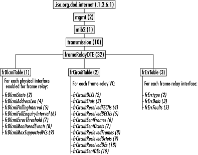
Figure D-6. The frame relay DTE MIB
RFC 2115 also defines the DLCI textual convention (data type) as an integer ranging from 0 to 8,388,607. In practice, most networks use DLCIs ranging from 0 to 1,023.
DLCMI Table
The first
table contains data about the Data Link Connection Management
Interface (DLCMI). For each frame relay physical interface, it
reports on LMI parameters. Objects in this table begin with
frameRelayDTE.frDlcmiTable.frDlcmiEntry
(32.1.1). Here is a list:
-
frDlcmiState(RFC-defined enumerated type) This object reports the LMI type in use on the interface. The most common values are
itut933a(5) for the ITU Q.933 Annex A specification andansiT1617D1994(6) for the ANSI T1.617a-1994 Annex D specification.
-
frDlcmiAddressLen(RFC-defined enumerated type) This object reports the length of the address field in bytes, although, it is an enumerated type. Its possible values are
twoOctets
Get T1: A Survival Guide now with the O’Reilly learning platform.
O’Reilly members experience books, live events, courses curated by job role, and more from O’Reilly and nearly 200 top publishers.

