Setting Up the Breadboard
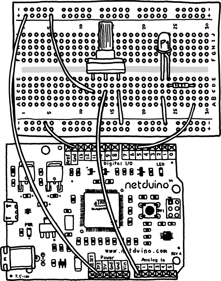
First, connect the 3.3V header from your Netduino to the voltage rail column of your breadboard. The voltage rail is on the side of the breadboard and is typically designated by a red line running alongside it. If you’ve rotated the breadboard as in Figure 6-1, which shows the completed connections, the rails will be on the top and bottom.
If you don’t have a rail that’s marked red, or if your breadboard has only one rail on each side, pick one rail to use as the voltage rail. To do this, plug a wire into the 3.3V header on your Netduino and then into any of the header holes in the breadboard’s voltage rail column.

Figure 6-1. Connecting the potentiometer and LED
When you provide power to a rail on the side of a breadboard, all of the holes in that column will become power supplies. Columns on the sides of breadboards are internally connected to provide this feature.
Note
Some large breadboards add multiple power rails. If this is the case with your breadboard, you may need to connect rail segments with wire to extend your power source.
Now that you’ve supplied 3.3V power to the breadboard’s power rail, you need to provide a return path for the electricity as well. Connect one of the GND (ground) headers from your Netduino to one of the header holes in the ground rail column of your breadboard. The ground rail is typically next to the power rail and designated ...
Get Getting Started with Netduino now with the O’Reilly learning platform.
O’Reilly members experience books, live events, courses curated by job role, and more from O’Reilly and nearly 200 top publishers.

