Chapter 1. Introduction
FPGA stands for field programmable gate array. That mouthful is simply trying to tell you that you can program an FPGA over and over (field programmable) and that it is more or less just a large array of logic gates (gate array).
Unless you already know what all that means, it is still not very helpful, so let’s break it down a little more. An FPGA belongs to a family of devices known as programmable logic devices. These devices allow you to design a digital circuit, and the device will become that circuit. This works by configuring small blocks (known as slices) to perform logic functions and connecting them together to implement your larger design. A more detailed description of how this all works is covered later. You can reconfigure the FPGA as many times as you want, and each time it will become the new circuit without needing to physically change anything!
In this chapter, we will explain a little more about what FPGAs are and what they are good at. We will also walk you through all the steps to set up the necessary software on Windows or Linux. Unfortunately, Macs are not supported by Xilinx’s tools, but you can work through a virtual machine running a compatible operating system. You can do with this with VirtualBox and Ubuntu, both of which are free. With a working environment, we will work through a basic project that will turn on an LED when a button is pressed.
The Mojo
Throughout this book, we will be using the Mojo and its IO Shield. The Mojo, shown in Figure 1-1, is an FPGA development board that is relatively inexpensive and requires only a computer and a micro USB cable to use. Unlike many other FPGA development boards, it is fairly minimal, with most of the FPGA’s pins broken out onto easy-to-use 0.1″ headers (a total of 84 digital I/O pins).
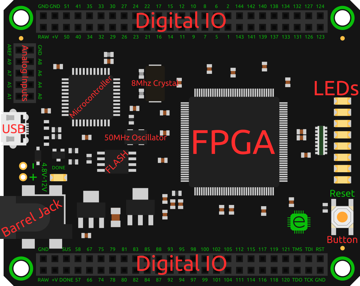
Figure 1-1. The Mojo
The Mojo also has an Arduino-compatible microcontroller whose main function is to program the FPGA over USB. However, once the FPGA is programmed, the microcontroller can be used as an ADC (eight analog inputs are broken out) and a USB-to-serial interface for your FPGA designs. Beyond the other bare necessities such as a 50 MHz oscillator, the Mojo features eight LEDs and a button (commonly used as a reset).
The I/O on the Mojo is all at 3.3 V and is not 5 V tolerant. Power can be supplied via the USB port, the barrel jack, the two holes, or the RAW input on the large headers. The supplied power should be between 4.8 V–12 V, with 5 V being the recommended voltage. You can connect an external power supply and the USB port at the same time, as the USB port is protected by a diode.
You can find more information and order the Mojo from Embedded Micro.
The IO Shield, shown in Figure 1-2 is an add-on board that stacks on top of the Mojo. It features 4 7-segment LED digits (like the display on your microwave), 24 LEDs, 24 switches, and 5 buttons. It is a great board for working through example projects. You can find more information and order your own from Embedded Micro.
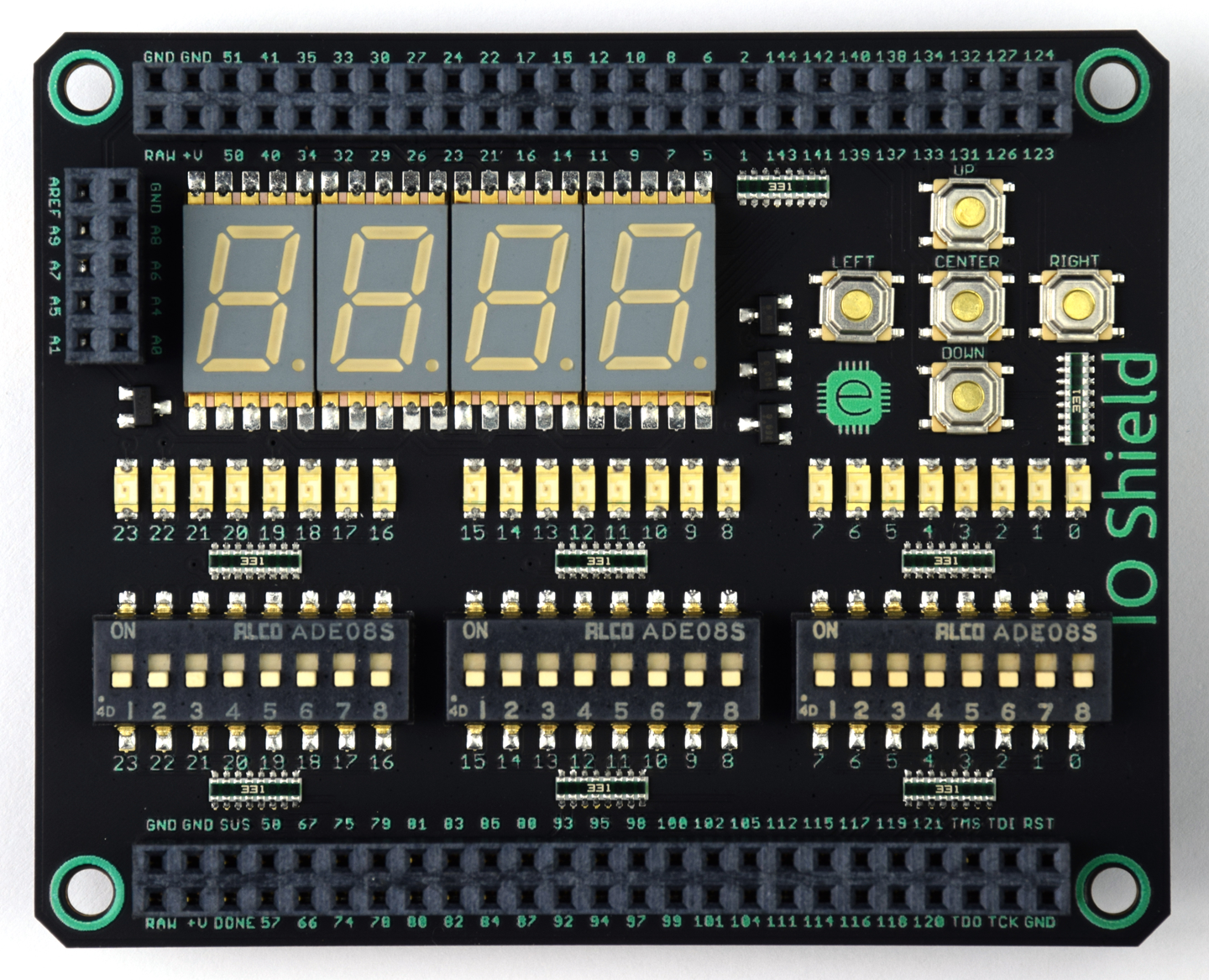
Figure 1-2. IO Shield
FPGAs Versus Microcontrollers: A Comparison
FPGAs and microcontrollers are often compared. This is especially true for people coming from a background of working with boards such as the Arduino or Raspberry Pi. An analogy that I particularly like is to think of a microcontroller as a person. People are flexible. You can teach someone to do almost any task, and his arms and hands are capable of manipulating basically anything. However, people can really focus on only one thing at a time, and unfortunately, we have only two hands. An FPGA, on the other hand, is like an assembly line. You can tailor it specifically for the exact job it needs to do. You can have many stages in the line that are all working at the same time, independent of one another.
FPGAs have been becoming more popular recently and have started appearing in more mainstream news. It used to be that if you wanted to improve the performance of an application, you simply bought or waited for a faster processor. However, in recent years, even though Moore’s law continues, processor performance has largely stalled with the extra transistors being used to cram more cores into a single chip. Because of this, people have started turning to FPGAs to accelerate tasks by creating custom hardware.
When you are working with FPGAs, you are designing hardware, not software. To make this a little clearer, let’s look at something that could be done with either an FPGA or a microcontroller: turning on an LED when you press a button. If you were to do this with a microcontroller, such as an Arduino or Raspberry Pi, the code to do this would read the button input, and if it is pressed, turn the LED on, and otherwise turn it off. This would keep happening over and over in a loop. Read button, update LED, read button, update LED, and so on. The problem with this is that the processor is now spending all of its time keeping the LED up to date with the current value of the button.
If you did the same project with an FPGA, you could simply connect the LED and the button through the FPGA. Since they are connected, there is no loop, and there is no code; the LED just turns on when the button is pressed. Now, if you wanted to change it up an, say, turn on the LED when the button is not being pressed, with a microcontroller you just change the test condition. However, with an FPGA, you can simply insert a NOT gate between the LED and button.
With the microcontroller, the processor is fully busy with this trivial task. What happens when you want it to also do something else, such as read other inputs or perform calculations? The processor has to juggle the tasks, spending only finite amounts of time on each one. As the complexity of your other code grows, the amount of time the processor has to spend checking the button and updating the LED shrinks, making it take longer and longer for the LED to turn off after you press the button.
FPGAs are not like this. Instead, with an FPGA, since it is all hardware, the circuit you designed to read the button and update the LED will operate completely independently of anything else you throw in your design. You could have another part of the FPGA crunching some serious numbers, but the LED will still be just as responsive as before.
Although you can usually do the same task with a microcontroller or an FPGA, there is usually a clear better choice. Things that require a lot of complex decision-making or sequential operations are commonly better candidates for microcontrollers. Things that can be done in stages or have a regular set pattern are great for FPGAs. This is just a rule of thumb, but the takeaway is that custom hardware and a processor fill different needs, and it’s often great to have both (and the Mojo does).
Another powerful feature of FPGAs is that they can read or write every I/O pin every clock cycle. With a microcontroller, you are typically limited to reading registers of 8 or 32 bits that correspond to I/O pins. If you need to sample more pins, you need to do it over multiple cycles, which may not be ideal. This makes it really easy to drive things that require a lot of I/O, such as LED matrices or a ton of servos. It’s also possible to read and write I/O pins at much higher rates. The FPGA on the Mojo is capable of I/O speeds up to 950 MHz; that’s 950 million reads or writes a second! Compare this to a typical Arduino’s max I/O toggle rate of around 3–4 MHz (with a 16 MHz clock), and this is achievable only if you dedicate all the processing time to toggling the pin.
Table 1-1 summarizes some of the key distinctions.
| Micro | FPGA |
|---|---|
| Write software. | Design hardware. |
| Typically executes one instruction at a time. | All parts of your circuit can operate independently. |
| Fixed maximum clock speed. | Maximum clock speed is dependent on your design. |
| A handful of I/O pins that can be accessed in small groups (typically eight) at a time. | Many I/O pins that can all be accessed simultaneously. |
| Usually store programs in nonvolatile (persistent) memory. | RAM based and needs to be programed after power on (the Mojo does this automatically). |
| Often very power efficient with advanced sleep modes. | Power usage depends on your design but typically requires more than a microcontroller. |
| Fixed peripherals that limit the devices you can connect. | Can interface with virtually any digital device. |
So what can you do with an FPGA that you can’t with a microcontroller? In Chapter 12, we use seven microphones to detect the directions of potentially multiple sound sources. Figure 1-3 shows the layout of the microphones on the board. This is done by calculating the delays between all the microphones for various frequencies and piecing them together to get an image of the sounds around the microphone array. A crucial step is sampling all the microphones at exactly at the same time. With an FPGA, it is fairly trivial to exert precise control over I/O pins. Once the samples are gathered, the FPGA is capable of performing all the calculations incredibly fast. The result is a sensor that constantly listens to its surroundings, generating direction data at over 80 Hz (limited by the sample acquisition time and not the processing time).
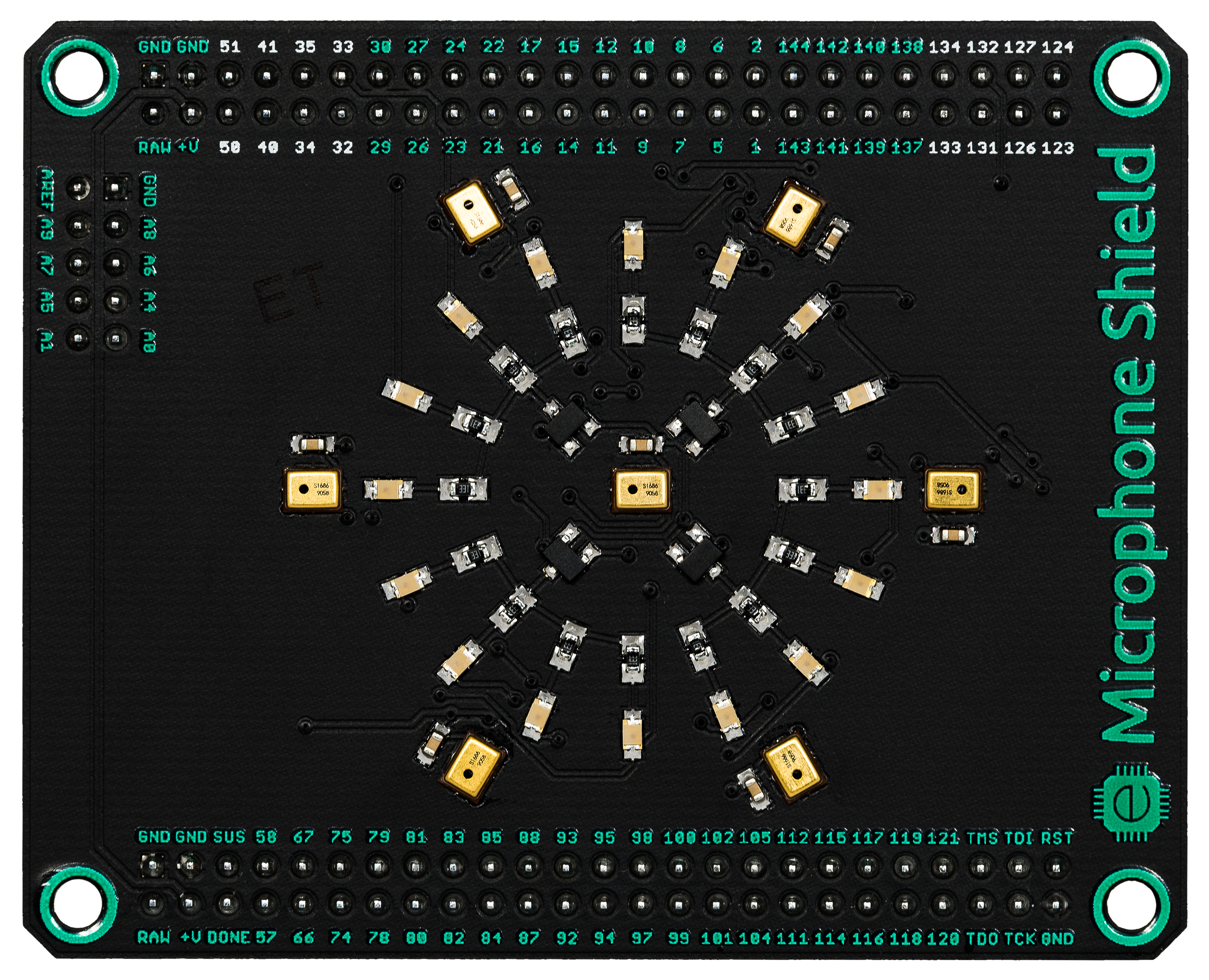
Figure 1-3. Microphone Shield
One of my favorite projects with the Mojo was a hexapod, shown in Figure 1-4. A hexapod is a 6-legged robot that usually has 3 servos per leg (18 total) plus 1 or 2 more for the “head.” Controlling all these servos can be pretty tricky. Many people have made hexapods without using FPGAs. However, even if all you want to do is make the hexapod walk, you still need to get external servo controllers to control that many servos. With an FPGA, you simply add a servo controller as part of your FPGA design, without the need for any external hardware. With an FPGA, every single I/O pin can control a servo. What made the FPGA in this project really necessary was the addition of a 2-megapixel camera (1,600 x 1,200) that took 15 pictures per second (nearly 29 million pixels per second!). The images from the camera were streamed directly into the FPGA, which performed blob detection (to look for red objects). By having the robot detect red objects, it was able to move its body and “watch” a red ball as someone moved it around. You can check it out in action on YouTube.
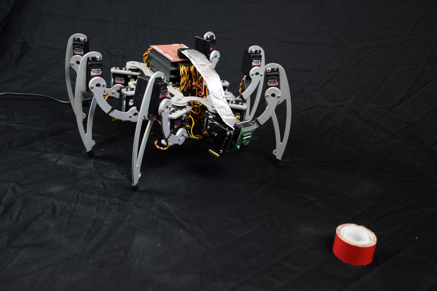
Figure 1-4. Hexapod
Setting Up Your Environment
The first step on your journey to becoming a digital hardware master is to install all the necessary tools. The FPGA on the Mojo is a Spartan 6 XC6SLX9 from Xilinx. Because of this, you need to download and install Xilinx’s tools to synthesize (build) your projects into configuration files (often called bit files) for the FPGA. Xilinx’s tools are a bit clunky, so we will be using the Mojo IDE to do all the work. Although you won’t need to use Xilinx’s tools directly, the Mojo IDE relies on them to build your designs.
Warning
The tools require you to be using Windows or Linux. If you’re using Windows, Windows 7 or newer is recommended. Although Windows 8 and above isn’t officially supported by the tools, it should still work with some minor workarounds. Most versions of Linux should work fine, but CentOS is known to have issues with setting up the Mojo and is not recommended. Ubuntu and its derivatives should work out of the box.
If you have a Mac, you can run Linux in a virtual machine or boot Linux from a USB drive. You can do the same for Windows if you have a license. If going this route, I recommend VirtualBox and Ubuntu. Both are free and known to work.
Installing ISE
ISE is the name of the tool Xilinx provides to build projects for the Spartan 6 family of FPGAs. Xilinx has a newer tool called Vivado, but that doesn’t support Spartan 6 devices.
Unfortunately, the installation process for ISE is a bit complicated. You are required to make an account with Xilinx to verify what you are using ISE for and where you live (export restrictions are imposed by the US government). ISE is a fairly large program. The download file is just over 6 GB, and the actual installation requires an additional 16 GB or so of space. After it is installed, you will then need to license it. The FPGA on the Mojo is covered by Xilinx’s free WebPACK license, but you still have to get the free license.
Head over to the Xilinx Downloads page. You need to download version 14.7 of ISE. This is the latest and final version. It should already be selected. Scroll down past the Multi-File Download: ISE Design section to ISE Design Suite. In this section, select the full installer for your platform (Linux or Windows). You will likely be prompted to fill out a survey on your reasons for downloading it. Then you will be asked to sign in. Create an account to continue with the download.
If you are on Windows, you need a way to extract the TAR file. Some TAR extractors don’t like this archive and fail to extract the entire thing. 7-Zip is known to work and is free. You can download it from the 7-Zip website.
With the files extracted, you need to start the installer. On Windows, double-click the xsetup executable. On Linux, you need to run xsetup with root privileges:
sudo ./xsetup
Once in the setup, accept all the license agreements. On the page that asks which edition to install, select ISE WebPACK, as shown in Figure 1-5.
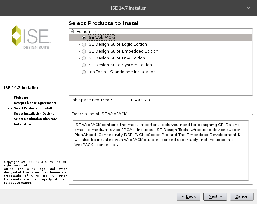
Figure 1-5. ISE edition selection
The next page, shown in Figure 1-6, asks which components you want to install. Make sure that Acquire or Manage a License Key is selected. If you are on Linux, make sure Ensure Linux System Generator Symlinks is also selected, as shown in Figure 1-7. You can uncheck the other options. They won’t hurt anything if you install them, but they aren’t needed. If you run into trouble with the installer, you can try to uncheck “Use multiple CPU cores for faster installation,” as it has been reported to cause problems in rare circumstances.
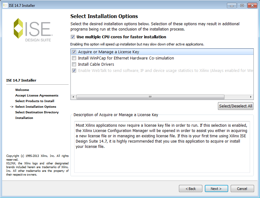
Figure 1-6. ISE installation options for Windows
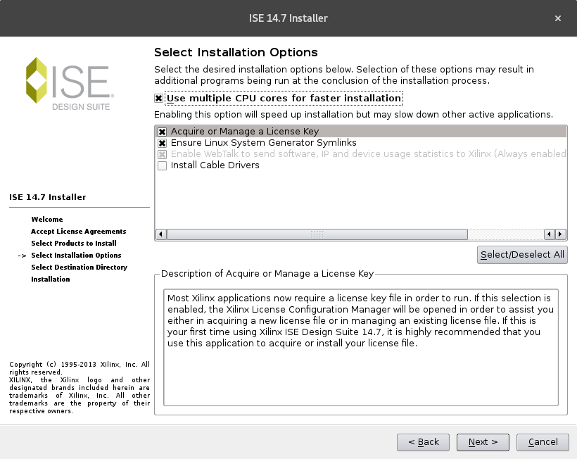
Figure 1-7. ISE installation options for Linux
On the next page, leaving the installation path as the default will make things a little easier later, but feel free to change it as long as you remember where it is.
Warning
If you are using Windows 8.1 or Windows 10 on a 64-bit machine and encounter problems, check out Embedded Micro’s ISE Installation Tutorial for other OS specific fixes.
Once the installation is complete, a new window to set up a license should open. If for whatever reason it doesn’t, you can manually open it by launching ISE and going to Help → Obtain a License Key.
On Windows, you can double-click the ISE icon that should now be on your desktop. On Linux, if you installed ISE to the default directory, you can run the following commands to launch it on a 64-bit system:
source /opt/Xilinx/14.7/ISE_DS/settings64.sh
/opt/Xilinx/14.7/ISE_DS/ISE/bin/lin64/ise
To launch ISE on a 32-bit system, use the following:
source /opt/Xilinx/14.7/ISE_DS/settings32.sh
/opt/Xilinx/14.7/ISE_DS/ISE/bin/lin/ise
In the Xilinx License Configuration Manager, shown in Figure 1-8, select Get Free Vivado/ISE WebPack License and click Next.
A little dialog box showing your system’s information pops up. Click Connect Now to open a web browser to acquire the license. If the button fails to open a browser, you can go to the license page directly.
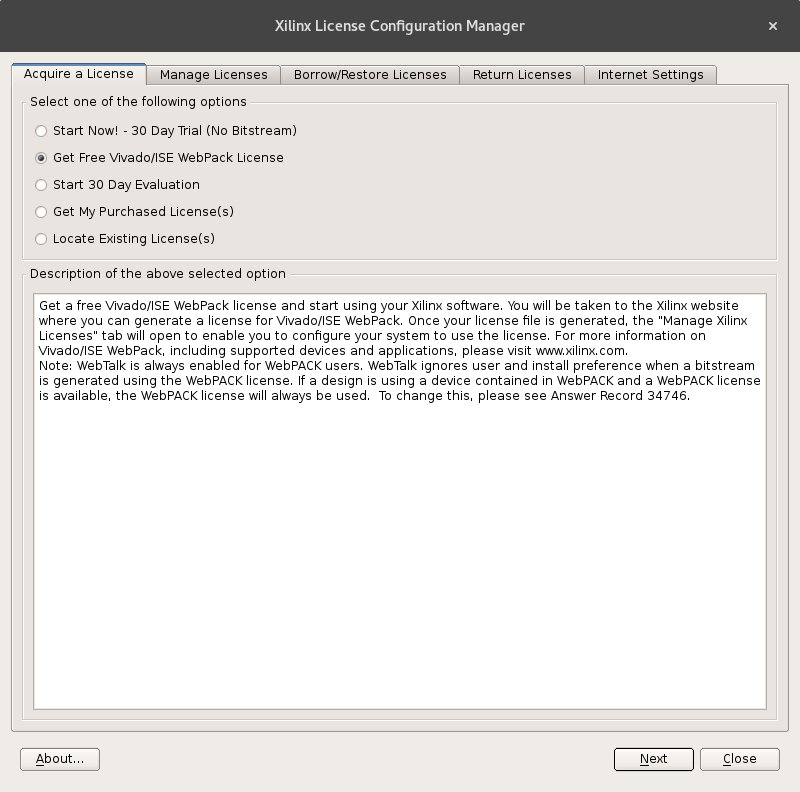
Figure 1-8. Select the WebPack license
You need to log into your Xilinx account again. When you are on the Product Licensing page, shown in Figure 1-9, select ISE WebPACK License and click Generate Node-Locked License to create your license. If you don’t see this option, you may have already generated a license before. In this case, head over to the Manage Licenses tab and download your existing license by using the tiny download button in the bottom-left corner.

Figure 1-9. Generate the WebPACK license
Click through the little pop-up window until the license is created and you are taken to the Manage Licenses tab. On this page, you should see your newly generated license. To download it, click the tiny blue arrow in the lower-left corner, as shown in Figure 1-10.
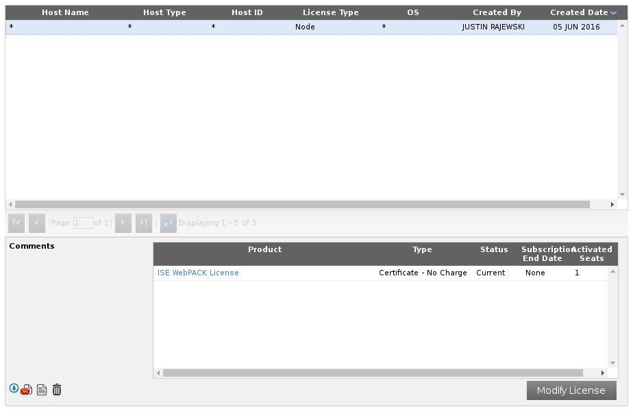
Figure 1-10. Click the little arrow in the bottom-left corner to download your license
A file named Xilinx.lic should be downloaded.
Back in the Xilinx License Configuration Manager, navigate to the Manage Licenses tab, if you’re not already there, and click Load License. Locate the Xilinx.lic file you just downloaded and select it. With the license loaded, the license manager should look like Figure 1-11.
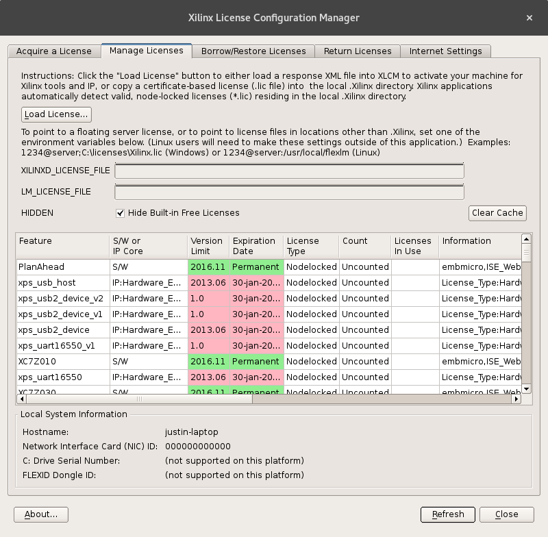
Figure 1-11. License manager with the WebPACK license loaded
Note that it might not look exactly like this, but ISE_WebPACK and PlanAhead should now be green.
ISE should now be ready to build your projects. You can close any ISE-related windows still open.
Installing the Mojo IDE
Installing the Mojo IDE is substantially simpler than setting up ISE. Head over to Embedded Micro and download the latest version. If you are on Windows, the installer is the recommended way to go.
The installer is pretty straightforward. Just follow the instructions until everything is installed. At the end of the installation, it should also install the necessary drivers.
On Linux, you just have the files and you can place them anywhere you want. You also need to have a JRE version 7 or newer to run the IDE. If you are using Ubuntu, you can install it by entering the following command:
sudo apt-get install openjdk-7-jre-headless
You also need access to serial ports. Again on Ubuntu, you can use the following to add yourself to the dialout group to get permission:
sudo usermod -a -G dialout`whoami`
In the Linux Mojo IDE files, there is a folder named driver with a file 99-mojo.rules. You should copy this file to /etc/udev/rules.d/. This ensures that you have permission to connect to the Mojo and prevents Ubuntu from thinking it is a modem and locking it up for a while whenever it is plugged in.
You should log out or restart your computer to make sure all these changes take effect.
Mojo IDE Settings
Before you create your first project, you need to tell the Mojo IDE where you installed ISE and what serial port the Mojo connects to.
Launch the Mojo IDE. If you installed it using the Windows installer, you should have a Start Menu entry and/or a desktop icon that you can use to launch it. If you downloaded the Windows files, you can double-click the mojo-ide.exe file after extracting the archive. On Linux, you need to run the mojo-ide script. This can be done with the following command:
./mojo-ide
You will be greeted by a welcome dialog box that has a little info about the version of the IDE you downloaded. You can get this welcome dialog back by going to Help → About Mojo IDE.
Go ahead and plug in the Mojo if you haven’t already. You need to figure out what serial port the Mojo is connected to. On Windows, you need to open the Device Manager. Launch the Control Panel and navigate to Hardware and Sound. You should then see Device Manager under Devices and Printers.
In the Device Manager, expand Ports (COM & LPT). You should see an entry such as Mojo V3 (COM3), as shown in Figure 1-12. The number following COM may be different. This is the port it is connected to. Remember this.
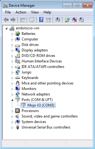
Figure 1-12. The Mojo is connected to COM3. The COM port number may be different for you.
On Linux, the Mojo will most likely connect to /dev/ttyACM0 or /dev/ttyUSB0. If you have more than one USB-to-serial device, the last number may be nonzero. You can list the ports on your computer with the following command:
ls /dev/tty*
If you unplug the Mojo and list the ports, and then plug it back in and list them again, the new one is what the Mojo is connected to.
Back in the Mojo IDE, open the Serial Port Selector by going to Settings → Serial Port and select the correct serial port, as shown in Figure 1-13.
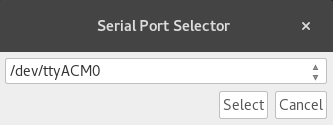
Figure 1-13. Select the serial port you found in the preceding step
The last step is to tell the IDE where to find the Xilinx tools. If you installed them in the default location, C:\\Xilinx\14.7 on Windows or /opt/Xilinx/14.7 on Linux, then you can skip this step because the IDE will check these by default. Otherwise, go to Settings → ISE Location and locate the 14.7 directory in your installation.
Everything should now be good to go! It’s time to start your first project.
Get Learning FPGAs now with the O’Reilly learning platform.
O’Reilly members experience books, live events, courses curated by job role, and more from O’Reilly and nearly 200 top publishers.

