October 2012
Intermediate to advanced
218 pages
5h 13m
English
Modern on-chip wireless transceivers usually use zero-IF, also called direct conversion or low-IF architectures because both are well suited to system integration by avoiding the use of external RF filters as are seen in the superheterodyne case.
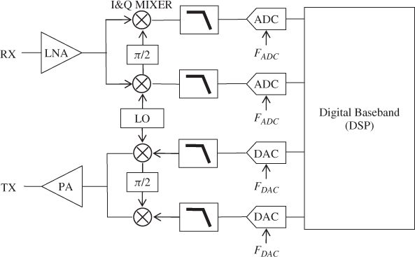
Figure 2.1 presents a simple schematic overview of zero-IF and low-IF AFE architectures. The RF analog receiver is composed of a LNA fixing its sensitivity, a LO and a quadrature mixer for frequency down-converting the signal around DC (zero-IF) or in low-IF, and finally anti-alias filtering and ADC for sampling and digitizing the baseband signal. The RF analog transmitter is composed of a DAC with reconstruction filtering for converting the baseband digital signal into analog, a LO and a quadrature mixer for frequency up-converting the signal to RF, and finally a PA for delivering the required transmit power.
Figure 2.1 Zero-IF or low-IF transceiver architecture
In this chapter we will especially focus on the principal impairments present in the RF AFE:
From the description of these imperfections we derive mathematical models ...
Read now
Unlock full access


 O’Reilly covers everything we've got, with content to help us build a world-class technology community, upgrade the capabilities and competencies of our teams, and improve overall team performance as well as their engagement.I wanted to learn C and C++, but it didn't click for me until I picked up an O'Reilly book. When I went on the O’Reilly platform, I was astonished to find all the books there, plus live events and sandboxes so you could play around with the technology.I’ve been on the O’Reilly platform for more than eight years. I use a couple of learning platforms, but I'm on O'Reilly more than anybody else. When you're there, you start learning. I'm never disappointed.I'm always learning. So when I got on to O'Reilly, I was like a kid in a candy store. There are playlists. There are answers. There's on-demand training. It's worth its weight in gold, in terms of what it allows me to do.