Once the PCB has been fabricated and checked carefully to ensure that all pads and tracks are intact and properly etched, do the construction a step at a time and check everything as you go. Do a continuity test between the ground pads and the ground pin on the power connector.
Start construction by soldering in the power connector and the voltage regulator and its support components, including the power LED if you’ve included one with your regulator.
Soldering is very easy to do well and very easy to do badly. The basic skills are easy to learn. Becoming a wizard with the soldering iron is not hard to achieve.
Note
Safety First
The most important thing to note about solder is that it contains lead. Therefore, all soldering should be done in a well-ventilated work area, and you should avoid breathing the fumes! After soldering, wash your hands, especially before eating! Solder can splatter, so always wear protective eyewear and clothes.
Solder is a metal alloy with a relatively low melting point. It is used to bond components to circuit boards and forms a conductive join. There are two basic categories of soldering tool—the standard soldering iron and the rework station. Rework stations blow heated air through a small nozzle and are primarily used with surface-mount components. However, it is relatively straightforward to solder all but the finest of surface-mount components using a standard soldering iron. You don’t necessarily need the more expensive rework stations.
The key to soldering well is to control the heat and the amount of solder that flows onto component pins. Too much heat can damage a component (especially sensitive integrated circuits) and can overheat solder as well. Read the datasheets to determine the maximum temperature (and duration) that the components can take, and ensure that your soldering iron does not exceed that. Variable-temperature irons allow you to set the temperature, thereby avoiding overheating. The tip of your soldering iron should be thin, allowing you to do fine work. An old-style iron with a large, bulky tip (intended for electrical work) is not appropriate for soldering electronics.
Warning
Whenever you solder your PCB, make sure that it is not powered! The tip of a soldering iron is grounded, and touching this to a pad with volts on it is not a good idea!
Similarly, when inserting or removing socketed components, ensure that the system is powered down. Most semiconductors do not appreciate being plugged into a live system.
There should be enough solder to make a good contact, but not so much that it bulges up or, worse, shorts a neighboring pin (Figure 4-20).
Tip
During the Apollo/Saturn missions, NASA found that teaching their technicians the correct way to solder saved them several hundred pounds in takeoff weight.
When soldering through-hole components (such as DIP-packaged chips or connectors), place the component into its hole and ensure that it is mounted correctly and sitting flat. To begin, solder one pin only, then check that the component is still seated correctly before doing the remaining pins. With the iron in one hand and a thin strand of solder in the other, bring the two together so that they meet at the pin to be soldered. Within a second, the solder will flow around the pin and you will have a good join. As soon as the solder begins to flow, remove both the iron tip and the solder strand.
Common mistakes when soldering are to heat the component pin for several seconds before applying solder (causing the component to become too hot) or to apply the solder directly to the iron and then dab the molten solder onto the pin.
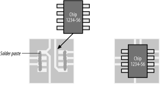
Soldering surface-mount components requires a different procedure. If you’re using a rework station, you will need to use solder paste. This is sold in a large syringe. Solder paste easily dries out inside the syringe, so ensure that you seal the end when it is not in use. Before soldering a surface-mount chip, place a thin squirt of solder paste along each row of pads on the PCB. Too much paste can flow under the chip and short out when you solder, so keep the application light. You can always add a small quantity later. Place the chip onto its PCB pads, ensure that it is lined up correctly, then use the rework station to apply heated air (Figure 4-21). Too much airflow will either shift the chip off its correct orientation or, worse, blow solder paste underneath. Since solder paste is electrically conductive, this is not a good thing. Too little heat will result in poorly soldered joints, whereas too much heat can easily overheat and damage the chip. It is something of an art to get it just right, and so it’s best to do considerable practice before tackling the real thing.
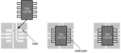
Surface-mount chips can also be soldered using a standard iron, although it’s not recommended for really finely spaced chip pins. Unlike the technique with the rework station, solder paste is applied after the chip is in place. To begin, before putting the chip on the PCB, use the iron and either strand solder or solder paste to place a small dab of solder directly onto one of the pads where the chip is to be mounted. Place the chip in position, aligning it carefully, and then use the iron to heat the pin resting on the solder dab. The dab will melt and fix the chip in place. Check the alignment again to ensure that the chip did not shift. If it did, reheat the pin again, and carefully shift the chip as appropriate. Once you are happy with the alignment, place a thin squirt of solder paste down each row of pins and as far from the edge of the chip as possible. Too much paste will flow between the pins, creating shorts, so keep it light. Gently and quickly run the tip of the soldering iron down each row of pins. The solder paste will melt and flow as you go and bond the chip to the PCB (Figure 4-22).
Solder is a metal alloy and incorporates a flux to assist flow. When heating the solder, it is common for the flux to separate and flow out onto the surrounding PCB, leaving a thin brown residue. Excess flux can be removed using special solvents, available from most electronics hobby stores and suppliers. Flux removers can be nasty stuff, so keep them away from skin and plastics and use in a well-ventilated work area. Flux residue is removed for cosmetic reasons only, and this will make your circuit boards look more professional to your customers. However, as it is for appearances only and since flux solvents are not good for either you or the environment, if you can avoid using them, please do so.
Note
A note on pronunciation
If you are a resident of North America, solder is pronounced “sodder.” If you live anywhere else in the English-speaking world, you will pronounce it as “sol-der.” So, Americans, be advised that if you say the word as “sodder” to non-Americans, they may not know what you’re talking about. Instead, they make think you’re confessing to strange and unspeakable acts, rather than talking about bonding metals together.
Get Designing Embedded Hardware now with the O’Reilly learning platform.
O’Reilly members experience books, live events, courses curated by job role, and more from O’Reilly and nearly 200 top publishers.


