Complete Mind-Controlled Robot
Now that we have every part working and tested, it should be easy to put it together, right? Wrong.
Even though reading constant stream of packets from the dongle works with LEDs, it’s a different case for turning the servos. LEDs, being semiconductors, take negligible time to change state. Servos move things that have mass, and are very slow compared to LEDs.
The previous attention routine assumed it will be called at suitable intervals. Here, we have to make an attention-reading function that can both be called very often and survive slight pauses.
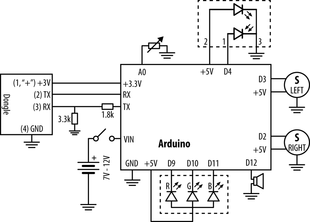
Build the final circuit (Figure 2-33) and upload mindcontrol.pde.

Figure 2-33. Circuit diagram for complete robot, mindcontrol.pde
// helloattention.pde - Show attention level (EEG) with LED color. // (c) Kimmo Karvinen & Tero Karvinen http://MindControl.BotBook.com /* Disconnect TX and RX jump wires from Arduino when uploading from IDE. Turn robot on, then in a couple of seconds turn headband on. */ const int redPin = 9; const int greenPin = 10; const int bluePin = 11; const int tinyLedPin = 13; const int speakerPin = 12; const int servoRightPin = 2; const int servoLeftPin = 3; const int linePin = 4; const int potPin = A0; const float potMin = 14.0 - 1; const float potMax = 236.0 - 5; int tinyLedState = HIGH; // percent variables, 0.0 to 1.0: float tr = -1.0; float attention = 0; float speed = 0.0; void setup() ...
Get Make a Mind-Controlled Arduino Robot now with the O’Reilly learning platform.
O’Reilly members experience books, live events, courses curated by job role, and more from O’Reilly and nearly 200 top publishers.

