When the founding engineers of Juniper decided to create routers, they took the view of forwarding packets as quickly as possible (line rate) with services enabled, which spawned the marketing decree “Service without Compromise.”
All Juniper Networks devices that run on the Junos operating system share the same common design philosophy, which is to have a clean separation of the control and forwarding planes. In the high-end devices (for example, M-series routers, MX edge devices, and Data Center SRXs), this separation is created in hardware, whereas the other devices (J-series routers and Branch Office SRXs) maintain this division in software. The forwarding plane is referred to as the Packet Forwarding Engine (PFE), and the control plane is called the Routing Engine (RE).
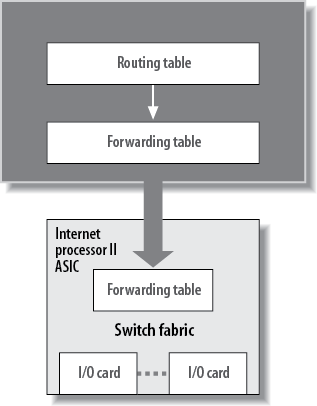
The RE’s primary functions are to manage the PFE, control the device’s software (Junos operating system), manage the command-line interface (CLI), provide troubleshooting tools, and maintain the route tables (both the route table and the route forwarding table). The forwarding table, a subset of the route table, is passed down to the PFE and is used to forward traffic. In this way, the RE never has to be directly involved in packet forwarding, which allows more resources for the actual control functions (see Figure 1-1). One example of the benefits of separating the control and forwarding functions is the ability to issue “traceoptions” commands (similar to debug) without degrading the throughput performance of the router.
Junos is pretty cool once you understand it. It creeps up on you, especially if you’re coming from another vendor or from Cisco IOS. That’s because the designers of Junos put tremendous thought into making a stable, robust, and scalable operating system for networking devices. They were able to learn from previous vendors’ mistakes and created an operating system that other companies will forever use as their model.
The core philosophy of Junos was to create a modular and stable operating system. The modularization was created by the use of software daemons, and the stability was achieved by choosing a well-known, open source, and stable kernel of FreeBSD. This kernel is usually hidden from the user, but many features of FreeBSD have been ported to the command line of Junos.
Note
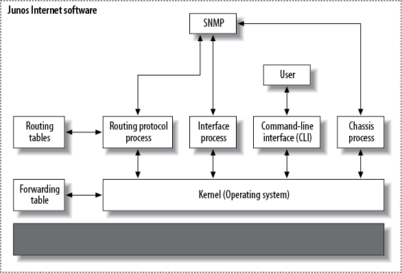
The kernel also maintains the forwarding table synchronization between the RE and the PFE.
Riding on top of the kernel are all the fully independent software
processes for routing, CLI, interfaces, and so forth. Figure 1-2 shows a small subset of these
processes; you can show a complete list in the device by issuing
the show system processes
command.
These processes are fully independent, so a failure of one process does not affect the other. For example, Figure 1-2 shows the Simple Network Management Protocol (SNMP) process pulling information from the interface, chassis, and routing processes. If this SNMP process fails or contains a software bug, it affects only this process and not the others. This is a major shift from other routing vendors that operated monolithic code where one change in the interface code could affect just about anything without reason.
Every Juniper Networks device running Junos is created from the same code base. Since all devices do not share common hardware, a new image has to be created for each device type. This is still Junos, however, with the same base feature set across all devices (routing, CLI, services, etc.). This means that there is a single image per version for all M/T-series devices and all MX edge devices, regardless of model number, and a single image per version for all J-series routers. The exception for image release is for the EX and SRX devices. There is an image for each of the EX models, and the SRXs have three individual images. The days of creating and maintaining large spreadsheets or lists for each router are now gone.
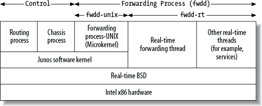
The differences in architecture between the M-series routers and the J-series routers show one of the reasons for the separation from a single image. The major difference in the J-series image is the inclusion of a software process called fwdd (forwarding devices daemon), which acts as the virtualized PFE. It is essentially a series of real-time threads operating over the kernel, as shown in Figure 1-3. Instead of an application-specific integrated circuit (ASIC) providing the functionality of the PFE, sockets and APIs interface with the kernel, providing a deterministic performance.
One of the key advantages of Junos is the single release train. This release train offers administrators of Juniper Network devices a predictable schedule for network upgrades. The release train follows a strict calendar for initial release, end of engineering support, and end of life. Table 1-1 is an excerpt from the Juniper Networks website.
Table 1-1. Junos release support
Product | FRS date | EOE | End of Life (EOL) |
|---|---|---|---|
Junos 10.4 | 12/08/2010 | 12/08/2013 | 06/08/2014 |
Junos 10.3 | 08/15/2010 | 05/15/2011 | 11/15/2011 |
Junos 10.2 | 05/15/2010 | 02/15/2011 | 08/15/2011 |
Junos 10.1 | 02/15/2010 | 11/15/2010 | 05/15/2011 |
Junos 10.0 | 11/15/2009 | 11/15/2012 | 05/15/2013 |
Junos 9.6 | 08/06/2009 | 05/06/2010 | 11/06/2010 |
Junos 9.5 | 04/14/2009 | 02/15/2010 | 08/15/2010 |
Junos 9.4 | 02/11/2009 | 11/11/2009 | 05/11/2010 |
Junos 9.3 | 11/14/2008 | 11/14/2011 | 05/14/2012 |
Junos 9.2 | 08/12/2008 | 05/12/2009 | 11/12/2009 |
Junos 9.1 | 04/28/2008 | 01/28/2009 | 07/28/2009 |
Junos 9.0 | 02/15/2008 | 11/15/2008 | 05/15/2009 |
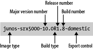
The first released shipments (FRS) are offered on a quarterly basis throughout the year. With each version of an image, there are releases and builds. The full naming convention for Junos releases is given in Figure 1-4.
Once a new version of Junos is issued, it undergoes multiple maintenance releases (for example, 10.0R1.8, 10.0R2.5, and 10.0R3.1). For any version, Juniper Networks recommends the latest maintenance release for a device, and the website provides a list of recommended releases for various equipment.
Juniper recognizes three levels of support for a Junos version:
- End of Engineering (EOE)
Active engineering support is provided during the period covering the current version and the next two versions, or 18 months from the first released shipment. Because the versions are released on a quarterly basis, active support is typically available for 9 months after first release shipment, which essentially means that no further maintenance releases are created for the version after this date.
- Juniper Technical Assistance Center (JTAC)
JTAC provides troubleshooting and workaround support for identified problems in a version from the time that EOE begins until two further versions are released or up to an additional year.
- End of Life (EOL)
Once EOL is reached for a version, JTAC typically requests that the customer update his or her image. If support is still requested, it is provided on a “commercially reasonable effort basis.”
Note
To assist customers who see no need to upgrade Junos on a regular basis, Juniper Networks has created what is called a Junos Extended End of Life (EEOL) release. These versions, which provide additional time for engineering and JTAC support, are released in the fourth quarter. EEOLs provide three years of engineering support and an additional six months of JTAC support.
In addition to the first shipment releases and the maintenance releases, Juniper also provides service and incident releases. These releases are not for general distribution, but might be recommended by an engineer or JTAC to solve specific problems. Service releases (for example, jinstall-ex-4200-10.0S6.1-domestic) are created to address specific problems found in an image and span the time between builds. Internal releases (for example, junos-srx5000-10.1I20100513_0739_schung-domestic) are often troubleshooting tools created by Juniper Network engineering when investigating a problem and trying different fixes. The problems solved by service and internal releases are incorporated into the next general release builds.
Note
According to some Juniper forums, service (S) releases are the recommended releases for specific devices deployed in certain scenarios. Until the newer versions of Junos are tested and verified, these network engineers are more comfortable with the S release.
The tool that will most often be used to configure and troubleshoot Juniper devices is the command-line interface (CLI). The Junos software CLI is one of the most user-friendly and feature-rich in the industry. Most administrators spend years attempting to master other router vendors’ CLIs, whereas Junos software can be mastered in just a few hours.
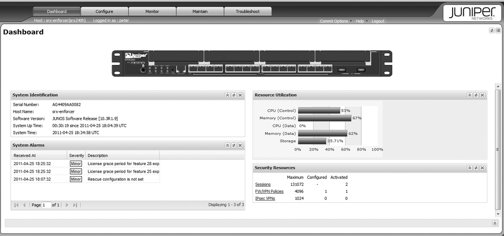
Other configuration methods do exist, such as a web GUI called J-Web (see Figure 1-5), which is available on all Juniper devices. The J-Web is enabled by default on most enterprise devices and can be activated for all devices. It’s a robust way of monitoring and configuring your devices, and it even has a point-and-click CLI component. Note that the operation of J-Web is beyond the scope of this book, so all configuration examples are shown via CLI commands instead. Learn the CLI first, and the J-Web is a snap to implement.
The CLI has two modes: operational and configuration. Operational mode is where you can troubleshoot and monitor the software, router, and network. Configuration mode is where the actual statements for interfaces, routing protocols, and others are placed.
Note
Every command that can be run in operational mode can also be
used in configuration mode with the additional keyword run. For example, if the show route command is issued in
operational mode, it can be issued as run
show route in configuration mode.
When a user first enters the router via Telnet, Secure Shell
(SSH), or direct console access, the user sees a login
prompt. After entering the correct username and password, the user is
placed directly into the operational mode. Operational mode is designated by
the > (chevron)
character at the device prompt of
username@hostname. As
shown here, user doug logs into a
router called Hops:
Hops (ttyd0)
login: doug
Password:
--- Junos 10.4R1.9 built 2010-12-08 16:25:40 UTC
doug@Hops>
An exception to this automatic placement into operational mode
occurs when you log in as user root. In this case, you are placed into the
shell (designated by the percent sign) and will have to start the CLI
process manually:
Hops (ttyd0) login: root
Password:
--- Junos 10.4R1.9 built 2010-12-08 09:22:36 UTC
root@Hops% cli
root@Hops>
Most of the commands that you run in operational mode are show
commands, which allow you to gather information about the routing
protocols, interfaces, and the device’s software and hardware. Ping,
traceroute, telnet, and ssh can also be performed from this mode.
Finally, some very Junos-specific commands, such as request, restart, and test, can be issued. Request commands
perform system-wide functions such as rebooting, upgrading, and
shutting down the device. Restart commands are similar to the
Unix-style kill commands, which allow you to restart certain software
processes. Test commands allow verifications for saved configuration
files, proactive testing of policies, and interface testing methods
such as BERT (bit error rate testing) and FEAC (far-end alarm and
control) loopbacks.
Warning
You should use the restart
command with great caution! Depending on the software process being
restarted, the consequences could be severe. Restarting the SNMP
process would probably get you a slap on the wrist, but restarting
the routing process could be a reason to go into hiding on a remote
island!
To actually configure the Junos device, enter configuration mode
by typing the word configure in
operational mode. The device prompt changes to the octothorpe (#)
symbol:
doug@Hops> configure
Entering configuration mode
[edit]
doug@Hops#
By default, multiple users can enter the configuration mode on a device and make changes at the
same time. To avoid any issues that may arise, you can use
the configure exclusive
or configure private command. The
former command allows only a single user to configure the router,
whereas the latter command allows multiple users to change different
pieces of the configuration. If you use configure exclusive, no other users can make
changes to the configuration besides the single user who entered
exclusively. Using private mode, each user will get a copy of the
current configuration and only the changes that they make will be
applied. If two users attempt to make the same change, such as adding
an IP address to the same interface, the change is rejected and both
users will exit configuration mode to resolve their conflict by some
other means.
In configuration mode, you can add configuration by using
a set command. For
example, to enable the Telnet server application on the device, issue
this command:
doug@Hops# set system services telnetOther useful commands in the configuration mode are:
deleteOpposite of the
setcommand, this subtracts configuration items:doug@Hops#
delete system services telnetreplace patternPerforms an exact match and replace for a string in the configuration:
doug@Hops#
replace pattern 10.1.1.1/32 with 10.1.1.1/24insertIn a configured list (rules or policies), allows an item to be moved from the bottom of the list to a different position:
doug@Hops#
insert policy permit_all before policy deny_allsaveWrites the configuration to a file named in the command:
doug@Hops#
save test_configurationeditMoves the user to a different level of the configuration:
[edit] doug@Hops#
edit system services[edit system services] doug@Hops#exitMoves the user to the next level up in the configuration (a user can also use the
upcommand), or if the user is at the top of the configuration, it will put the user into operational mode:[edit system services] doug@Hops#
exit[edit system] doug@Hops#up[edit] doug@Hops#exitdoug@Hops>renameAssigns a new name to a configured object:
doug@Hops#
rename interface ge-0/0/1 to interface ge-10/0/1copyCopies the attributes of a configured object to another object:
doug@Hops#
copy interface ge-0/0/1 to ge-0/0/2commitPerforms a semantic and completeness check of the changes made to the configuration, and if the changes pass these checks, the changes are written to the device’s running configuration:
doug@Hops#
commit
A full treatment of the capabilities and operation of the CLI is beyond the scope of this book, as mentioned in the Preface, but the operational capabilities of the CLI are explored throughout this book by building and showing hundreds of examples.
Let’s continue our tour of Junos in the enterprise with the routing features found in most Junos-based devices, keeping in mind that many of the details of these features and example configurations are found in later chapters.
The first product produced by Juniper Networks was an IP router, and since that initial launch, all Juniper Networks products based on Junos have had routing capabilities at their core.
The principles for routing transit traffic are handled in the same way in all devices:
The routing functions are divided between the RE and the PFE.
The RE is responsible for determining the best route to a prefix.
This information is passed to the PFE.
All transit traffic is handled by the PFE.
When the RE determines that the conditions in the network have changed enough to warrant a change in packet routing, a new set of instructions is forwarded to the PFE.
The network prefixes and the routes to them are kept in a set of tables stored in the RE and the PFE. Chapter 5 explores the full set of routing tables and the use for each, so here the focus is only on the table that is used for IPv4 traffic. This table is called the inet.0 table, and it contains a list of all known network prefixes and the attributes for each prefix. The attributes maintained for a prefix are determined by the way that prefix was learned by the device. So if a prefix was entered as a static route, only the information that was manually entered would be stored with the prefix, or if the route was learned via a routing protocol (e.g., OSPF), the additional information associated with the prefix would be stored with the route. The inet.0 table is also referred to as the master routing table when this table is identified from another table for static routes. The following shows example output of an inet.0 table:
doug@Hops> show route
inet.0: 23 destinations, 23 routes (22 active, 0 holddown, 1 hidden)
+ = Active Route, - = Last Active, * = Both
1.12.1.0/24                *[Direct/0] 00:33:41
                                    > via ge-1/0/0.0
1.12.1.1/32                *[Local/0] 00:33:41
                                    Local via ge-1/0/0.0
10.255.66.0/24          *[OSPF/10] 00:32:53, metric 1
                                    > to 1.12.1.2 via ge-1/0/0.0
192.168.102.0/23      *[Static/5] 5d 02:42:28
                                    > to 192.168.71.254 via ge-1/0/0.0
This table has been reduced in size, but it shows that the device knows four prefixes. The prefix 1.12.1.0/24 is a directly connected network on interface ge-1/0/0.0, the interface ge-1/0/0.0 has an address of 1.12.1.1/32, prefix 10.255.66.0/24 was learned via OSPF from another device connected via interface ge-1/0/0.0, and the prefix 192.168.102.0/23 was statically added to the configuration.
The entries in the inet.0 table are analyzed, and the active
routes (all the routes in the preceding example are active, as indicated
by the *) are sent to the forwarding
table. The forwarding table is then sent to the PFE (refer to Figure 1-1). The forwarding
table does not contain the prefix attributes that are contained in the
inet.0 table, just the key elements for how to handle traffic destined
for a network prefix. The following shows an example forwarding table
entry:
doug@Hops> show route forwarding-table destination 10.255.66.1
Routing table: inet
Internet:
Destination        Type RtRef Next hop       Type Index NhRef Netif
10.255.66.0/24    user     0 1.12.1.2        ucst   286     2 ge-1/0/.0
The determination of which routes are sent to the forwarding table from the routing table follows a simple rule: the route must be the active route with the lowest cost and route preference. If a single prefix has multiple routes that have equal costs and preferences, one of the next hop interfaces is chosen in a pseudorandom manner (the exception to this is equal cost routing, explained in the next section).
Once this process is complete and all prefixes are loaded in the PFE, transit traffic can be handled. The destination address from an incoming packet is compared to the forwarding table, looking for the longest match. Once a match is found, the next hop and interface information are used to handle the egress processing for the packet. If no match is found for the destination address and no default route is established for the device, the packet is dropped.
The determination of which route gets sent to the forwarding table can be manipulated by other parts of the configuration. Most attributes of a prefix entry can be modified by policies and rules. These configurable features allow an administrator to customize how traffic is handled within the device.
Route policies can be applied as routes enter the routing table (import) or as routes are sent to neighbors (export). The policies can accept or reject routes, and for accepted routes, the attributes of the routes can be modified. When prefixes are learned by one routing protocol (for example, BGP) and wish to be advertised in another (say, OSPF)—a process known as route redistribution—a routing policy is used. If routes learned from one source are to be preferred to routes learned from another source, again, policies can be used to accomplish this. Full treatment of routing policies is found in Chapter 5.
Filter-based forwarding, which is similar to what other vendors call policy-based routing, allows incoming (ingress) or outgoing (egress) traffic to be compared to a set of match criteria defined in a filter. When the traffic matches the filter, the action defined in that filter area is applied to that packet. One such action would be routing the packet based on the rules of a nondefault routing table, allowing scenarios to be created where matching traffic is routed over a different set of next hops/links based on local policy rather than conventional longest match. In a simplistic example, privately addressed traffic can be sent to a private.inet.0 table where a default route shunts them to a specific next hop or server, while public addresses can be sent to the default inet.0 routing table.
Load balancing, or equal cost multipath (ECMP) routing, is turned off by default on Juniper devices. The default routing mechanism chooses a single next hop destination for every prefix, but load balancing can be configured on the devices and can be set either as a global feature for all traffic on the device or for specific traffic. The load-balancing algorithm uses a hash function to determine the link to use for traffic. The load balancing is on a per-flow basis and is calculated based on a configurable Layer 3 and/or Layer 4 hash. A configuration example for ECMP and a full explanation can be found in Chapter 5.
Multitopology routing enables the router to participate in an environment that has different routing rules for different traffic types. It uses the concepts of filter-based forwarding with configured topologies. The topologies create different forwarding information bases (FIBs) for each traffic type. Each FIB can use a different instance of a routing protocol as well as different attributes (costs and preferences) for prefixes. When traffic enters the device, the filter-based forwarding allocates the traffic to a specific FIB. The information in that FIB is used to route the traffic. This capability, when deployed across an enterprise network, allows a single network infrastructure to support multiple traffic types on logically separate networks. Configuration examples for multitopology routing and a full explanation of its capabilities are discussed in Chapter 6.
Let’s quickly define some of the more common switching features found in Junos devices. While the full details of these features and configuration examples are beyond the scope of this book, its companion volume, Junos Enterprise Switching, by Harry Reynolds and Doug Marschke (O’Reilly), is an excellent resource for both the administrator and the network designer.
The design of an enterprise network requires the use of routing, switching, and security devices. When Juniper decided to enter the enterprise market, it did so with the determination that these other networking requirements would be added to Junos. Today, Ethernet switching is a feature for the EX product line, the MX product, and the SRX product line. All of these products offer both Ethernet switching capabilities and IP routing capabilities in a single device.
The choice between switching and routing is dependent on the
nature of the traffic and the device’s configuration. For the most part,
when both switching and routing are present, the device routes traffic
that is addressed (at the MAC layer) to it and switches all other
traffic. Switching features are configured in different devices in
different manners. For instance, in the high-end Data Center SRXs,
switching is enabled in what is called transparent
mode, whereas in the Branch Office SRX and EX switches,
specifying the Ethernet-switching
family on an interface enables switching.
Let’s look at some of the switching features you’ll likely encounter in enterprise networks.
Transparent mode is enabled for the high-end Data Center SRX Series Services Gateways (SRX 3xxx and 5xxx) via configuration mode and allows interfaces to operate in an Ethernet switch mode. The device can be configured to support both routed interfaces and switched interfaces. Transparent mode devices support options for flooding unknown MAC addresses, bridge domains (broadcast domains), and virtual LANs. The full capabilities of transparent mode can best be discovered in the book Junos Security, by Rob Cameron et al. (O’Reilly).
Learning MAC addresses is the means by which all Ethernet switching devices determine where to switch frames in a network. The size of the switching table is a measure of the power of the switching devices, and the Juniper switches support table sizes from 8,000 entries for the low-end EX2200 to 160,000 entries for the enterprise-level EX8200 (the MX edge routers are capable of having a million MAC addresses). When a frame is received that contains a destination MAC that is not in the forwarding table, that frame is flooded to all the interfaces of the specific bridge domain on the switch. Juniper switches support two flooding options for unknown traffic: conventional flooding and the more secure address resolution protocol (ARP) flooding capability.
Virtual switch constructs allow single Ethernet switches to support multiple logical divisions in an enterprise. These constructs include:
- Bridge domain
A bridge domain is defined by a virtual LAN (VLAN) and a group of interfaces that form a broadcast domain for Ethernet traffic. Multiple bridge domains can be created on a single platform, providing for a separation of traffic.
- VLAN
A VLAN allows traffic from a common community of interest to communicate in an Ethernet-switched environment. VLANs segment the traffic and provide security from other VLANs.
- Virtual chassis
A virtual chassis allows the interconnection of multiple physical switches to form a single administered unit. The individual switches act as a routing engine, a backup routing engine, or a line card in the grouping of switches.
Ethernet protocols govern the interaction of Ethernet switches in an enterprise network. They allow redundancy while avoiding broadcast storms, thereby bringing survivability to an Ethernet environment. The protocols supported by Juniper Networks switches running Junos are:
- Spanning Tree
Spanning Tree Protocol (STP) and its variations, RSTP and MSTP, operate between Ethernet switches to ensure a loop-free network. Multiple Spanning Tree Protocol (MSTP) incorporates the concepts of VLANs into the protocol, whereas Rapid Spanning Tree Protocol (RSTP) operates on a single VLAN but improves the time to recover from a network failure.
- Link Aggregation
Link Aggregation Control Protocol (LACP) and 802.3ad provide link aggregation capabilities for devices. Up to 16 links can be bound into a single bundle. This provides a high-bandwidth, survivable link between devices. Link aggregation also supports a MAC hashing function to support load balancing, which assures that traffic in a single flow follows the same link in the 802.3ad bundle.
Ethernet switching also supports a number of other capabilities on the Junos platforms, such as multicast support and 802.1X port-based authentication.
Let’s briefly cover the security features found in Junos-based devices, keeping in mind that the full details of these features and configuration examples are beyond the scope of this book. For in-depth coverage, seek out Junos Security.
Starting in the mid-9 release of Junos, SRX devices and J-series routers incorporated session-based processing, which is the single unique feature in the SRX Series devices.
Note
For the J-series routers, Junos 9.3 incorporated the first of these security features, and 9.4 offered no packet-based option for the J-series. For the Data Center SRXs, Junos 9.2 was the first flow-based offering, whereas Junos 9.4 was the first flow-based offering for the Branch Office SRXs.
Rather than processing each packet as an independent entity, packets are grouped together in unidirectional flows, and flows are paired into a session. Consequently, a majority of the processing is performed at the session level rather than the packet level. Once a session is created and additional packets are received that match the session parameters, the session attributes are used to handle the packet.
Session-based processing enables these security features found in Junos:
- Security zones
A security zone is a set of interfaces and the addresses found on those interfaces that are grouped together as a single security element. All security policies are written from a security zone to a security zone.
- Stateful security policies
Junos-based security devices are prudent security devices, starting with the fact that all traffic through the device is blocked unless explicitly permitted. Security policies are created to determine what traffic is allowed and what should be blocked. The match criteria for traffic are the source and destination addresses and the application-level identification found in the traffic. Policies are unidirectional at the session level. They are defined for sessions that are initiated from a single zone destined for a zone. Reverse traffic that is associated with the session does not need a reverse policy, but sessions that follow the reverse path do need a policy matching the session’s direction.
- Application layer gateways (ALGs)
ALGs provide proxy support for certain applications, allowing the proper operation of applications that would not operate successfully through a firewall. One example of such an application layer protocol is the session initiation protocol (SIP) used in voice over IP (VoIP) implementations. When used in a secured scenario, SIP requires a firewall to parse its messages and perform actions on behalf of the SIP server and client. These actions could include network address translation, opening additional ports through the firewall, and providing proxy services. The services are all performed by the ALG defined for SIP. ALG support is enabled by default on Junos-related security products, except for the Data Center SRXs.
- Network Address Translation (NAT)
One of the most common security features, NAT allows an administrator to hide the inside of the enterprise network from prying eyes. The Junos-based security systems support dynamic and static NAT, as well as source-based and destination-based NAT.
- Intrusion Detection and Protection (IDP)
IDP is a sophisticated security feature that relies on attack signatures and observation of enterprise traffic. Junos security devices can perform either a passive alarm-only role or an active alarm and deter role. The IDP features require an administrator to monitor the state of the signature database and tune the IDP rules to the traffic that is seen on the enterprise. IDP features are integrated into the SRX product line or can be deployed in purpose-built IDP devices.
- User authentication
User authentication and user access control enable a Junos security device to activate rules based on the users that are creating traffic. Teaming Juniper network access control devices with the Junos security devices creates a dynamic pair for recognizing users and modifying the security policies to accommodate these users.
- Virtual private networks (VPN)
IPsec VPNs are a mainstay for site-to-site and remote access security. They provide encryption and authentication services as well as data integrity capabilities for the transmitted traffic. The Junos security devices offer a full range of IPsec VPN capabilities.
- Screen functions
When the full capabilities of IDP are not warranted, the screen functions can be considered an IDP-lite capability. These attack-deterrent functions protect the device from common hacks and denial of service attacks. They are implemented at the zone level and provide a first line of defense.
- Unified Threat Management (UTM)
UTM is a set of security features that includes anti-virus protection, anti-spam filtering, URL filtering, content filtering, and user authentication. These services are available on the J-series routers and the lower-end Branch Office SRX Series.
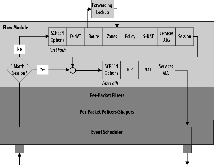
When session-based processing was introduced into Junos, a new traffic-processing algorithm was needed because the existing packet-based processing performed in hardware would not suffice for this new paradigm. Figure 1-6 shows the order for processing traffic in a session-based environment. Class of Service (CoS) and filter functions are performed first and last at the line card level. For incoming traffic, session matching is performed next. If an existing session is found for the traffic, “fast path” processing is performed based on the attributes of the session. In the fast path, screen functions are performed, NAT and ALGs complete their actions, and the traffic is sent for egress processing.
If the packet is not part of an existing session, new session processing is performed. This entails the initial routing, policy lookup, any NAT that needs to be performed, ALGs, and finally entering the information into the session table. Once this is complete, the packet is processed as it is in the fast path for egress.
Get Junos Enterprise Routing, 2nd Edition now with the O’Reilly learning platform.
O’Reilly members experience books, live events, courses curated by job role, and more from O’Reilly and nearly 200 top publishers.
