This schematic, while a little hairier, is still pretty simple to parse. Let’s give it a
shot:
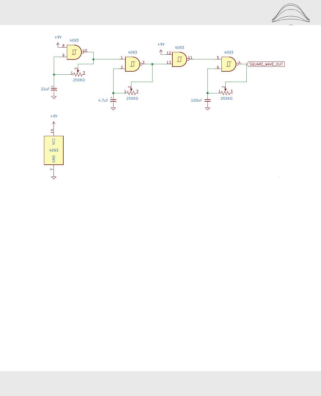
• First, let’s set up pins 8, 9, and 10 to oscillate. We can do this by attaching pin
8 to +9 V, a capacitor between pin 9 and ground, and a potentiometer between
pins 10 and 9.
• Our output from pin 10 will attach to pin 1. Add a capacitor between pin 2 and
ground and a potentiometer between pins 2 and 3.
• Our output from pin 3 will go directly into pin 13. Attach pin 12 to +9 V so the
NAND gate is set up as an inverter.
• Finally, send our output from pin 10 to pin 5. Add a capacitor between pins 6
and ground and a potentiometer between pins 4 and ...


