However far modern science and technics have fallen short of their inherent possibilities, they have taught mankind at least one lesson: Nothing is impossible.
Instrumentation is a big word, with a broad and rich set of meanings. Like most words with multiple interpretations, the exact meaning is largely a function of the context in which it is used, and who is using it.
Instrumentation can be defined as the application of instruments, in the form of systems or devices, to accomplish some specific objective in terms of measurement or control, or both. Some examples of physical measurements employed in instrumentation systems are listed in Table 1-1.
Table 1-1. Examples of physical measurements
Acceleration | Mass |
Capacitance | Position |
Chemical properties | Pressure |
Conductivity | Radiation |
Current | Resistance |
Flow rate | Temperature |
Frequency | Velocity |
Inductance | Viscosity |
Luminosity | Voltage |
As natural human language is an imprecise communications medium, contextually sensitive and rife with multiple possible meanings, the preceding definition still covers a lot of territory. To a process engineer, it might mean pressure sensors, heater elements, solenoid-controlled valves, and conveyors. A research scientist might think of lasers, optical power sensors, servo-driven X-Y microscope stages, and event counters. An electrical engineer might define instrumentation as digital voltmeters, oscilloscopes, frequency counters, spectrum analyzers, and power supplies.
Generally speaking, whatever can be measured can also be controlled, although some things are more difficult to control than others (at least with our current technology). When a measured input value is used to generate a control output for a system, often referred to as the plant, the input may need to be modified, or transformed, in some way in order to match the operating parameters of the system. This might entail amplification, conversion from current to voltage, time delays, filtering, or some other type of transformation.
In this book, we will examine how to utilize computer-based instrumentation using readily available low-cost devices, along with the Python programming language (primarily), to perform various tasks in data acquisition and control. Using a high-level approach, this chapter introduces some of the basic concepts we will be working with throughout the rest of the book. It also shows some simple instrumentation examples. If you are not familiar with some of the concepts introduced in this chapter, don’t be overly concerned about it. We will discuss them in more detail later. The primary objective here is to lay some groundwork and introduce some basic terminology.
From a computer’s viewpoint, all data is composed of digital values, and all digital values are represented by voltage or current levels in the computer’s internal circuitry. In the world outside of the computer, physical actions or phenomena that cannot be represented directly as digital values must be translated into either voltage or current, and then translated into a digital form. The ability to convert real-world data into a digital form is a vast improvement over how things were done in the past.
In the days of steam and brass, one might have monitored the pressure within a boiler or a pipe by means of a mechanical gauge. In order to capture data from the gauge, someone would have to write down the readings at certain times in a logbook or on a sheet of paper. Nowadays, we would use a transducer to convert the physical phenomenon of pressure into a voltage level that would then be digitized and acquired by a computer.
As implied above, some input data will already be in digital form, such as that from switches or other on/off–type sensors—or it might be a stream of bits from some type of serial interface (such as RS-232 or USB). In other cases, it will be analog data in the form of a continuously variable signal (perhaps a voltage or a current) that is sensed and then converted into a digital format.
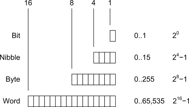
When referring to digital data, we mean binary values encoded in the form of bits that a computer can work with directly. Binary digital data is said to be discrete, and a single bit has only two possible values: 1 or 0, on or off, true or false. Digital data is typically said to have a size, which refers to the number of bits that make up a single unit of data. Figure 1-1 shows digital data ranging from a single bit to a 16-bit word. The size of the data, in bits, determines the maximum value it can represent. For example, an 8-bit byte has 256 possible unique values (if using only positive values).
For inputs from things such as sensor switches, the size might be just a single bit. In other cases, such as when measuring analog data like pressure or temperature, the input might be converted into binary data values of 8, 10, 12, 16, or more bits in size. The number of available bits determines the range of numeric values that can be represented. Although it’s not shown in Figure 1-1, binary data can represent negative values as well as positive values, and there is a standard format for handling floating-point values as well.
Analog data, on the other hand, is continuously variable and may take on any value within a range of valid values. For example, consider the set of all possible floating-point values in the range between 0 and 1. One might find numbers like 0.01, 0.834, 0.59904041123, or 0.00000048, and anything in between. The name analog data is derived from the fact that the data is an analog of a continuously variable physical phenomenon.
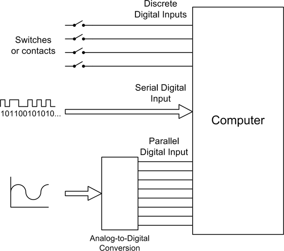
Figure 1-2 shows the various types of inputs that may be found in a computer-based data acquisition system. Switches are the equivalents of single binary digits (bits). A serial communications interface may be a single wire carrying a stream of bits end-to-end, where each set of 8 bits represents a single alphanumeric character, or perhaps a binary value. Analog input signals, in the form of a voltage or a current, are converted into digital values using a device called an analog-to-digital converter (ADC). We will take a close look at these devices—and their counterparts, digital-to-analog converters (DACs)—in Chapter 2.
Get Real World Instrumentation with Python now with the O’Reilly learning platform.
O’Reilly members experience books, live events, courses curated by job role, and more from O’Reilly and nearly 200 top publishers.


