Chapter 4
Impedance Matching in the Wideband Case
4.1 Appearance of Narrow and Wideband Return Loss on a Smith Chart
The methodology of impedance matching is basically the same between narrow and wideband cases. However, in the narrowband case, only one frequency needs to be taken care of in the process of impedance matching because a narrow bandwidth can be represented approximately by the central frequency. In the wideband case, instead of a single frequency, the entire wide bandwidth must be taken care of, which makes impedance matching somewhat difficult. In this chapter, we will apply the same process of impedance matching as in the narrowband case, but the main effort will to expand the skill from narrow to wide bandwidth. (The methodology of impedance matching in the wideband case introduced and discussed in this chapter was developed in 2005 by the author specially for a UWB (ultra wideband) system and has not been made public until now).
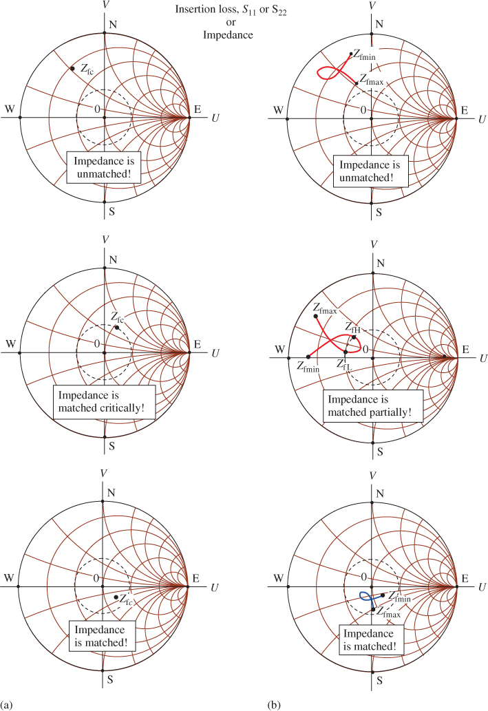
Figure 4.1 shows the difference of the return loss or impedance on the Smith Chart between the narrow and wideband cases. The dashed-line circle in each plot is the demarcation circle of return loss as mentioned in Chapter 3, where S11 or S22 = − 10 dB.
Figure 4.1 Appearance of return loss in the narrow and wideband cases. (a) Narrowband case. (b) Wideband case.

In the narrowband cases, as shown in Figure 4.1(a), the return loss or impedance ...
Get RF Circuit Design, 2nd Edition now with the O’Reilly learning platform.
O’Reilly members experience books, live events, courses curated by job role, and more from O’Reilly and nearly 200 top publishers.

