Chapter 13: Speciality of “Zero if” System
13.1 Why Differential Pair?
13.1.1 Superficial Difference between Single-Ended and Differential Pair
In the early years of electronic circuit development, only single-ended stages were studied and implemented. Gradually, it was found that some special features of performance could be achieved only by a differential pair instead of a single-ended stage or a double-balanced mixer. At present, both single-ended and differential pairs have been developed for most RF blocks, such as the LNA (low-noise amplifier), mixer, VCO (voltage-controlled oscillator), filter, and PA (power amplifier). In the recent years, a number of differential circuits have appeared in RF or RFIC designs, especially in “zero IF” or direct conversion communication systems.
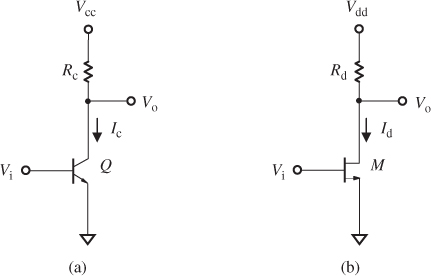
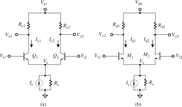
Without the input and output impedance matching networks, a single-ended stage is shown in Figure 13.1, and a differential pair is shown in Figure 13.2.
Figure 13.1 Typical single-ended block. (a) Bipolar single-ended stage. (b) MOSFET single-ended block.

Figure 13.2 Typical differential pair. (a) Bipolar differential pair. (b) MOSFET differential pair.

The differential pair appears as two single-ended blocks joined together with a common emitter or source resistor, Re or Rs, in a bipolar or a MOSFET ...
Get RF Circuit Design, 2nd Edition now with the O’Reilly learning platform.
O’Reilly members experience books, live events, courses curated by job role, and more from O’Reilly and nearly 200 top publishers.

