5.3 INTERCONNECTION NETWORK SWITCH ARCHITECTURE
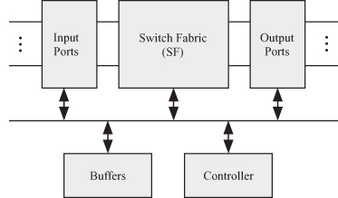
As was explained above, networks rely on switches to perform their functions. Thus, it is worthwhile to study the construction of switches in more detail. A switch is a hardware device that accepts messages or packets at its inputs and routes them to its outputs according to the routing information provided in the message header and the switch routing table. Figure 5.12 is a block diagram showing the main components of a switch. The switch has the following main architectural components:
1. Controller
2. Input ports
3. Switch fabric (SF)
4. Buffers
5. Output ports
Figure 5.12 Basic components of a switch.

Notice that although the switch is a part of the interconnection network, it also has its own switching network! Typically, it is called the SF. In the following discussion, we shall refer to the units of data communicated between processors as packets.
Controller. The controller controls the operation of the switch and routing packet streams through a lookup table that knows how to route a packet based on its source and destination processor addresses.
Buffers. The incoming packets must be stored within the processor since a certain delay is encountered while determining the packet route. Also, due to collisions, an incoming packet might not be able to access the desired output port and must wait for later routing. The ...
Get Algorithms and Parallel Computing now with the O’Reilly learning platform.
O’Reilly members experience books, live events, courses curated by job role, and more from O’Reilly and nearly 200 top publishers.

