Appendix
APPENDIX A.1 TWO-BIT BY TWO-BIT ADDER
Verilog code for a two-bit by two-bit adder:
module addition_2bit (inputA, inputB, outputA);

input [1:0] inputA, inputB;
output [2:0] outputA;

wire [2:0] outputA;

assign outputA = inputA + inputB;

endmodule
Verilog test bench to simulate the two-bit by two-bit adder:
module addition_2bit_tb ();

reg [1:0] reg_inputA, reg_inputB;
wire [2:0] wire_outputA;

integer i,j;

initial
begin
     for (i=0; i<4; i=i+1)
          begin
               reg_inputA = i;
for (j=0; j<4; j=j+1)
                begin
                         reg_inputB = j;
                         #10;
                    end
          end
end

addition_2bit addition_2bit_inst (.inputA(reg_inputA),
.inputB(reg_inputB), .outputA(wire_outputA));

initial
begin
     $monitor (“inputA %b%b inputB %b%b outputA
%b%b%b”, reg_inputA[1], reg_inputA[0], reg_inputB[1],
reg_inputB[0],
     wire_outputA[2], wire_outputA[1],
wire_outputA[0]);
end

endmodule

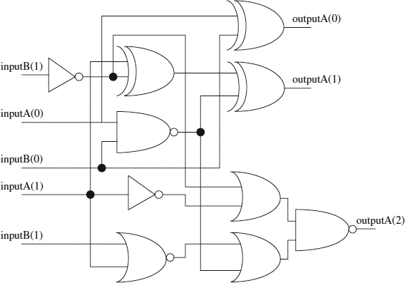
FIGURE A.1. Synthesized logic for the two-bit by two-bit adder.
Simulation results for simulating the two-bit by two-bit adder:
inputA 00 inputB 00 outputA 000 inputA 00 inputB 01 outputA 001 inputA 00 inputB 10 outputA 010 inputA 00 inputB 11 outputA 011 inputA 01 inputB 00 outputA 001 inputA 01 inputB 01 outputA 010 inputA 01 inputB 10 outputA 011 inputA 01 inputB 11 outputA 100 inputA 10 inputB 00 outputA 010 inputA 10 inputB 01 outputA 011 inputA 10 inputB 10 outputA 100 inputA 10 inputB 11 outputA 101 inputA 11 inputB 00 outputA 011 inputA 11 inputB 01 outputA ...
Get Verilog Coding for Logic Synthesis now with the O’Reilly learning platform.
O’Reilly members experience books, live events, courses curated by job role, and more from O’Reilly and nearly 200 top publishers.

