May 2005
Beginner to intermediate
398 pages
12h 12m
English
Inductors are passive components that are essentially coils of conductive wire. The schematic symbol for an inductor is shown in Figure 4-38. Inductance is measured in Henries, with an equation symbol "L" and a unit symbol "H."
Figure 4-38. Schematic symbol for an inductor
The voltage across an inductor changes the current flow through it, measured with the following relation:
V = L * dI / dt
Whereas applying a current to a capacitor caused the voltage to build across it, the opposite is true for an inductor. Applying a voltage across it builds current flow through it, and the resulting energy is stored in the inductor as a magnetic field. When the applied voltage is removed, the field collapses and returns the stored energy as a voltage spike.
Figure 4-39 shows a series R-L circuit.
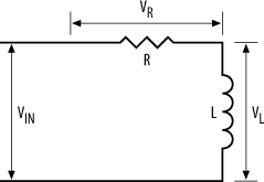
Figure 4-39. Series R-L circuit
The voltage across the resistor (VR) and the voltage across the inductor (VL) are shown in Figure 4-40. When a voltage is applied at VIN, the voltage across the resistor is initially small, whereas the voltage across the inductor is large. As the current flow through the inductor builds, the voltage across the resistor increases, while the voltage across the inductor diminishes accordingly.
Figure 4-40. Series R-L response to a step input
Figure 4-41 shows a series ...
Read now
Unlock full access


