Diodes are semiconductor devices that are extremely useful. They have the interesting characteristic that they will pass a current in one direction but block it from the other. They can be used to allow currents to flow from one part of a circuit to another but prevent other currents from "backwashing" where you don't want them.
The schematic symbol for a diode is shown in Figure 4-46. The arrow indicates the direction of conduction. The arrow represents the anode , or positive side, of the diode, while the bar represents the cathode , or negative side, of the diode. A higher voltage on the left of the component will allow current to be passed through to the right. However, a higher voltage on the right will be prevented from causing current flow to the left.
Diodes have a forward voltage drop when conducting. This means there will be a voltage difference between the anode and the cathode. For example, a diode may have a forward voltage drop of 0.7 V. If this diode is part of a larger circuit and the voltage at the anode is 5 V, then the voltage at the cathode will be 4.3 V.
Diodes come in a variety of shapes and sizes. Figure 4-47 shows a small power diode. The white stripe indicates the cathode (negative) end of the diode.
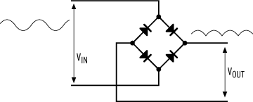
Diodes are useful for removing negative voltages from a signal, a process known as rectification . Four diodes may be combined to form a bridge rectifier, as shown in Figure 4-48. The bridge "flips" the negative components of the wave, so that only a positive voltage is present at the output. A capacitor on the output can be used to smooth the rectified wave.
Such configurations are commonly used on the power inputs of embedded computers and other digital systems. A voltage can be applied across the inputs on the left, with no regard as to which should be positive or negative. The bridge rectifier ensures that a positive voltage will always be conducted to the upper right, and at the same time current flow is returned from the lower right through the bridge rectifier to whichever lefthand connection is negative.
If you'll forgive the pun, the most commonly seen diode is the LED (Light Emitting Diode). The schematic symbol is shown in Figure 4-49, and a through-hole LED is shown in Figure 4-50. All diodes produce a small amount of light as a consequence of their operation (although you don't normally see it because of the diode casing); it's just that LEDs are especially good at it.
There is a limit to the amount of current that can pass through a LED. Exceeding this current will potentially damage or destroy the LED. For this reason, LEDs are used in conjunction with a current-limiting resistor. Figure 4-51 shows such a circuit. Some LEDs will incorporate a current-limiting resistor internally. However, most do not, so it is important to check the manufacturer's datasheet. Generally, you'll need to include the resistor, and calculating the required value (R) is easy.
Let's say that the LED has a forward voltage drop of 1.6 V and a current limit of 36 mA. We need to select a resistor that will limit the current flowing through the LED
to this value. In our circuit, the LED and resistor are in series, and the total voltage across them is 5 V. So, if the LED has a voltage drop of 1.6 V, then we can easily calculate the voltage drop across the resistor:
   VR = 5 - 1.6
        = 3.4 V
So, if the voltage drop across the resistor is 3.4 V, and we need to limit the current to 36 mA, then using Ohm's Law we can calculate a value for R:
   R = V / I
     = 3.4 / 0.036
     = 94.44 Ω
A 100 Ω resistor will therefore do fine and will result in a brightly glowing LED. If you want lower-intensity light, you just need to limit the current further, and you would therefore use a larger resistor. Note that since 36 mA is the maximum current the LED can handle, we will always need a resistor that keeps the current flow below this. Therefore, we always opt for a larger R.
The power that the resistor must dissipate is given by the relation:
   P = V * I
     = 3.4 * 0.036
     = 0.1224 W
Resistors are available with different power-dissipation ratings. It is important to choose a resistor with the correct rating. In this instance, we would use a 0.125 W resistor.
The ubiquitous power-on LED you see in your home appliances works in this exact same way. This simple LED circuit (or variations of it) drives the LEDs on your PC's front panel, on your VCR and DVD player, your cell phone, and a host of other appliances. Many traffic lights and railroad signals are replacing conventional bulbs with arrays of LEDs, as the LEDs last longer and produce more light (per area).
LEDs are available in red, green, yellow, blue, and white. The last two colors are very hard to produce and therefore relatively expensive.
There are two more types of diodes about which it is useful to know: Zener diodes and Schottky diodes (Figure 4-52).
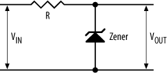
Zener diodes exhibit a characteristic known as dynamic resistance , or small-signal resistance . The voltage drop across a Zener diode will not change as the current through it changes. In effect, it acts as a variable resistor whose resistance is current-dependent. Zener diodes are commonly used to provide a reference voltage (Figure 4-53).
From Ohm's Law, we have:
(VIN - VOUT) = I * R
Now, if VIN changes, it logically follows that the current will also change. So we can modify our equation thus:
(VIN -
VOUT) =
I * R
The Zener acts as a source of dynamic resistance, which we'll designate Rd. Now what we have is effectively a voltage divider. So, our equation for VOUT is:
VOUT =
VIN * Rd / (R + Rd)
Schottky diodes are also known as hot-carrier diodes and behave like conventional diodes, save for a very small forward voltage drop. They are commonly used in power-supply circuits and signal rectification for this reason.
Get Designing Embedded Hardware, 2nd Edition now with the O’Reilly learning platform.
O’Reilly members experience books, live events, courses curated by job role, and more from O’Reilly and nearly 200 top publishers.


