May 2005
Beginner to intermediate
398 pages
12h 12m
English
So far, we have looked at how you can sense real-world effects and convert these into digital data. Now let's see how to do the reverse: take digital data and convert it into an analog signal by using a chip known as a Digital-Analog Converter (DAC). We'll also look at how you can produce an analog output using nothing more than a single digital I/O line.
All DACs have a digital input (a microprocessor bus, SPI, or I2C) and will provide you with one or more channels of analog output.
The Maxim MAX525 is an 11-bit DAC that interfaces to a host processor using SPI. It has four channels of analog output and incorporates output amplifiers on-chip. The inverting input of each amplifier is accessible so that you can alter their respective gains. A sample circuit for a MAX525 is shown in Figure 13-22.
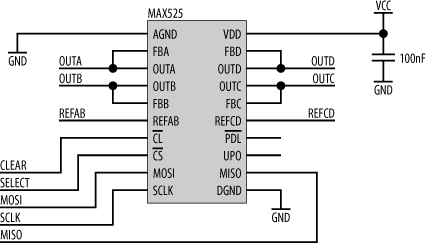
Figure 13-22. MAX525 circuit
The four analog output channels are OUTA, OUTB, OUTC, and OUTD. These are tied directly to their respective feedback inputs (FBA, FBB, FBC, and FBD) for standard unipolar operation. There are two voltage reference inputs, REFAB (for channel A and channel B) and REFCD (for channels C and D). These two reference inputs must be at least 1.4 V or more below VCC at all times. The output voltage for each channel is given by the relation:
VOUT = (VREF * code / 4096) * gainwhere code is the digital value written to that channel. In our sample ...
Read now
Unlock full access


