The Voltage Divider
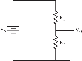
23 The circuit shown in Figure 1.7 is called a voltage divider. It is the basis for many important theoretical and practical ideas you encounter throughout the entire field of electronics.
The object of this circuit is to create an output voltage (V0) that you can control based upon the two resistors and the input voltage. V0 is also the voltage drop across R2.
What is the formula for V0? _____
R1 + R2 = RT, the total resistance of the circuit.
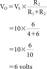
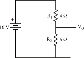
24 A simple example can demonstrate the use of this formula.
For the circuit shown in Figure 1.8, what is V0? _____

25 Now, try these problems.
What is the output voltage for each combination of supply voltage and resistance?
V0 = _____
V0 = _____
V0 = _____
V0 = _____
26 The output voltage ...
Get Complete Electronics Self-Teaching Guide with Projects now with the O’Reilly learning platform.
O’Reilly members experience books, live events, courses curated by job role, and more from O’Reilly and nearly 200 top publishers.


