Self-Test
These questions test your understanding of the concepts introduced in this chapter. Use a separate sheet of paper for your diagrams or calculations. Compare your answers with the answers provided.
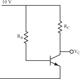
For the first three questions, use the circuit shown in Figure 4.30. The objective is to find the value of RB that turns the transistor ON. As you may know, resistors are manufactured with “standard values.” After you have calculated an exact value, choose the nearest standard resistor value from Appendix D, “Standard Resistor Values.”
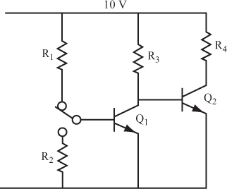
For questions 4–6, use the circuit shown in Figure 4.31. Find the values of R3, R2, and R1 that ensure that Q2 is ON or OFF when the switch is in the corresponding position. Calculate the resistors in the order given. After you find the exact values, again choose the nearest standard resistor values.
Get Complete Electronics Self-Teaching Guide with Projects now with the O’Reilly learning platform.
O’Reilly members experience books, live events, courses curated by job role, and more from O’Reilly and nearly 200 top publishers.


