3.3 Architecture
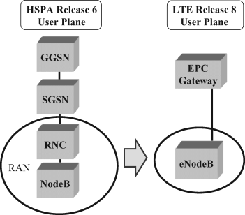
The LTE overall architecture has adopted the principle of flat radio architecture, as compared to the Release 6 HSPA architecture both radio and core side user plane handling can be handled in a single element, with one box core and one box radio, as shown in Figure 3.9. The key motivation is to ensure easy scalability to avoid having to make capacity upgrades to multiple levels like with the Release 6 case when the traffic is increasing. There have been also further developments on HSPA side in Release 7 to add another architecture option, as shown in Chapter 14, but in LTE there is only the option ‘all radio in the eNodeB’ being included in the specifications.
Figure 3.9 Evolution to the flat radio architecture with LTE.

Also the control plane design in the LTE radio is based on the single element radio access network principle, thus all the radio protocols terminate in eNodeB as shown in Figure 3.10. The connection to the core network is handled by S1 interface, which is divided in two to allow maximum scalability between the user plane and control plane processing needs. User plane uses S1-U interface while the control information between eNodeB and MME is carried on the S1-MME interface. For the support of Radio Resource Management (RRM) there is the X2 interface between the LTE eNodeBs. The X2 is mainly for the control plane purposes but also in connection ...
Get LTE Advanced: 3GPP Solution for IMT-Advanced now with the O’Reilly learning platform.
O’Reilly members experience books, live events, courses curated by job role, and more from O’Reilly and nearly 200 top publishers.

