50 CHAPTER 5
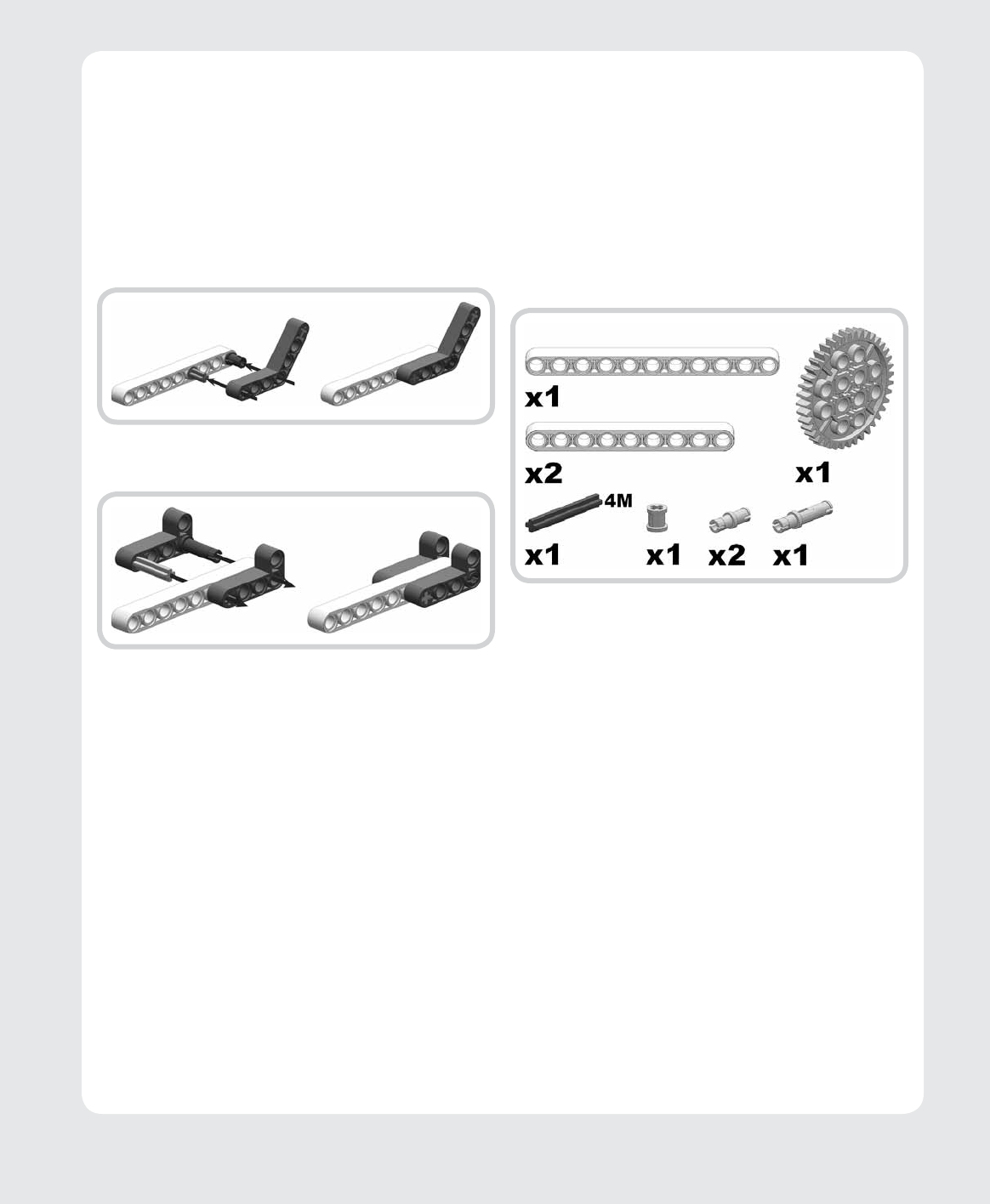
Figures 5-9 and 5-10 illustrate techniques involving
a combination of straight beams and angled beams. In
Figure 5-9, we extend a 9M beam using a 7M angled beam,
a friction peg (round-hole to round-hole), and a friction axle
peg (round-hole to cross-hole). Figure 5-10 shows how to
widen a beam with two 5M perpendicular angled beams
joined by a 3M friction peg and a 3M axle. Notice how the
3M axle connects all three pieces by passing through two
cross-holes and a round-hole. Note also the 4M overlap in
both techniques that adds robustness to the connections.
creating
dynamic
structures
All the previous techniques focused on creating ...


