MC-LAG Modes
This chapter has touched on the two different MC-LAG modes: active-standby and active-active. When MC-LAG was first released,
the only available mode was active-standby, which works on both DPC and MPC
line cards. Because it was the first mode to be released and because of
the simplicity of its design, the active-standby mode is generally more common.
With the introduction of Trio and MPC line cards, MC-LAG was upgraded to
support an active-active mode. This new
mode will only work using Trio-based line cards such as the MPC.
Active-Standby
The active-standby mode works
by selecting a PE router to be the active node while the other PE router
is the standby node. Only one of the PE routers can be active at any
given time. When a PE router is active, it will signal via LACP to the
CE router its child link is available for forwarding.

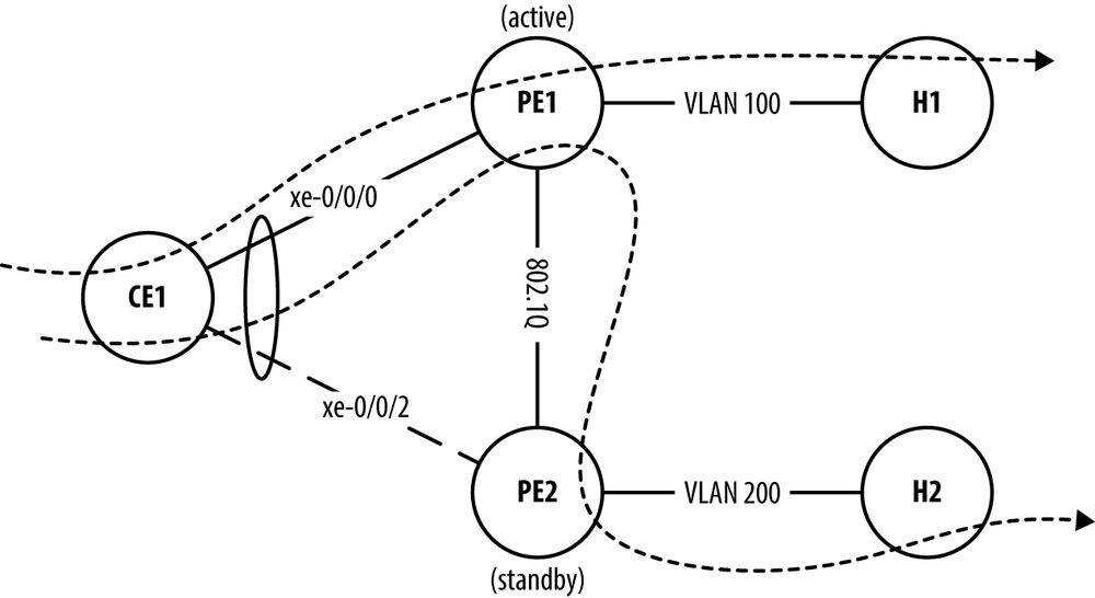
Figure 8-9. MC-LAG Mode Active-Standby.
Figure 8-9 illustrates MC-LAG
in the active-standby mode. In this
example, router PE1 is active and
PE2 is the standby node. This mode
forces all traffic through the active node PE1. For example, a frame destined to VLAN 100
would be forwarded to PE1 and then
directly to H1. A frame destined to
VLAN 200 would also be forwarded to PE1, then to PE2, and finally to H2.
Let’s take a look at the LACP information from the vantage point
of CE1:
{master:0}
dhanks@CE1-RE0>show lacp interfaces Aggregated interface: ae1 ...
Get Juniper MX Series now with the O’Reilly learning platform.
O’Reilly members experience books, live events, courses curated by job role, and more from O’Reilly and nearly 200 top publishers.

