Case Study
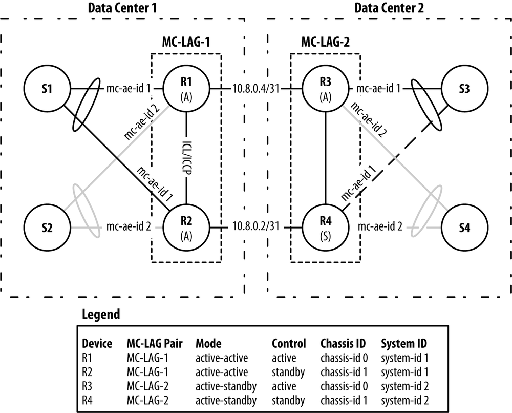
The best way to apply the concepts in this chapter is to create a case study that integrates many of the MC-LAG features in a real-world scenario. Using the book’s laboratory topology, it’s possible to create a two pairs of PE routers and CE routers, as illustrated in Figure 8-12.

Figure 8-12. MC-LAG Case Study Topology.
This case study will create two pairs of MC-LAG routers and two pairs of switches:
- MC-LAG-1
Routers
R1andR2will be in theactive-activemode. These are MX240 routers acting as the PE nodes.- MC-LAG-2
Routers
R3andR4will be in theactive-standbymode. These are MX240 routers acting as the PE nodes.- Switch Pair 1
Switches
S1andS2will be running vanilla IEEE 802.3ad and IEEE 802.1Q. These are EX4500s acting as the CE nodes.- Switch Pair 2
Switches
S3andS4will be running vanilla IEEE 802.3ad and IEEE 802.1Q. These are EX4200s acting as the CE nodes.On the far left and right are switches
S1throughS4. These switches are acting as vanilla CE devices connecting into their own MC-LAG instance. From the vantage point of each CE switch, it believes that it has a single IEEE 802.3ad connection going into the core of the topology. To mix things up, each MC-LAG instance will operate in a different mode. The MC-LAG instance forS1andS2will beactive-active, whereas the MC-LAG instance forS3andS4will beactive-standby.
This case study will move through all the ...
Get Juniper MX Series now with the O’Reilly learning platform.
O’Reilly members experience books, live events, courses curated by job role, and more from O’Reilly and nearly 200 top publishers.

