3.3 Eye Diagram
In Section 3.2 we investigated the propagation of transient signals (voltage step and pulse) on transmission lines. In digital base band circuitry, information is transmitted by a series of pulses. In practice a pulse has a more trapezoid than rectangular shape due to lower bandwidth.7
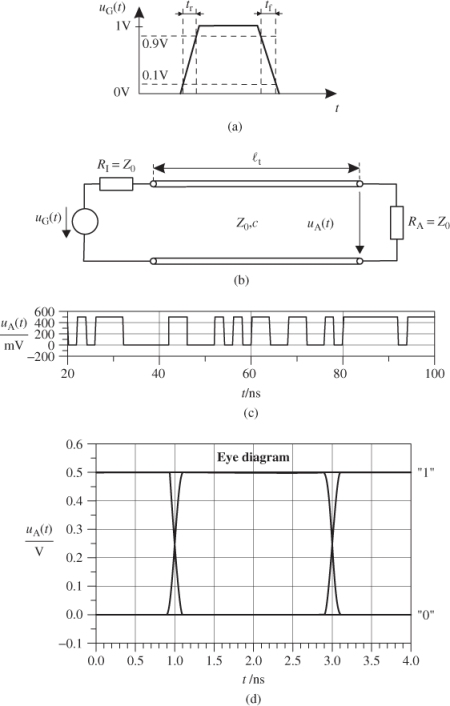
Commonly, the transition time from 10% to 90% of a signal amplitude change is referred to as rise time tr and the transition time from 90% to 10% is called fall time tf (see Figure 3.25a).
Figure 3.25 Eye diagram for a series of digital pulses on an ideal and matched transmission line.

If we transmit such a pulse signal over a matched, loss-less, non-dispersive transmission line the only effect we observe is time delay due to the finite speed of signals on the line (see Figure 3.25b).
3.164 ![]()
where the factor 1/2 is due to the voltage divider rule (at the input terminals we see half of the source voltage). We illustrate the effect by selecting a voltage source that generates a random sequence of logical ‘ones’ (higher voltage output) and logical ‘zeros’ (lower voltage output). Figure 3.25c shows as an example the unperturbed digital output voltage that equals (except for time delay and voltage drop) the source voltage.
A practical graphical tool to access the quality of a digital signal ...
Get RF and Microwave Engineering: Fundamentals of Wireless Communications now with the O’Reilly learning platform.
O’Reilly members experience books, live events, courses curated by job role, and more from O’Reilly and nearly 200 top publishers.

