6.8 Branchline Coupler
6.8.1 Conventional 3 dB Coupler
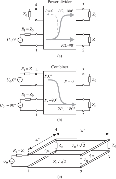
A branchline coupler is a four-port network that can be used either as a power divider or as a signal combiner. Figure 6.37a shows the power divider operation: the signal fed into port 1 is split into equal shares between port 2 and port 3. Port 4 is isolated. The signals at the output ports 2 and 3 are 90° out of phase. Figure 6.37b shows the combiner operation: Signals with equal magnitude but a phase difference of Δφ = 90° at port 1 and 4 are summed up at port 2. Port 3 is isolated.
Figure 6.37 Branchline coupler: (a) 3 dB/90° power divider, (b) combiner, and (c) basic design.

The branchline coupler consists of two series lines (characteristic impedance ![]() ) and two shunt lines (characteristic impedance Z0), each of which is a quarter wavelength long (see Figure 6.37c).
) and two shunt lines (characteristic impedance Z0), each of which is a quarter wavelength long (see Figure 6.37c).
The scattering matrix of an ideal branchline coupler (at the centre frequency f0) is given as
6.52 
Figure 6.38 shows a branchline coupler with microstrip lines. At the centre frequency the scattering parameters s11 and s41 are low. The transmission coefficients are s21 = s31 = − 3 dB indicating an equal power split. The phase difference between the output signals ...
Get RF and Microwave Engineering: Fundamentals of Wireless Communications now with the O’Reilly learning platform.
O’Reilly members experience books, live events, courses curated by job role, and more from O’Reilly and nearly 200 top publishers.

