4.7 Circular Waveguide
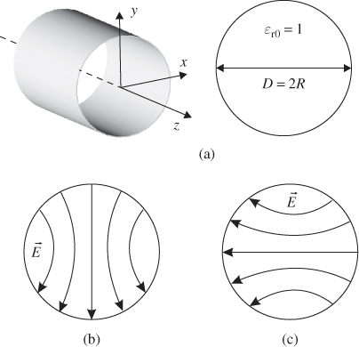
A circular waveguide consists of a hollow metallic cylinder with an inner radius R (see Figure 4.22a). In the inner air-filled volume of the cylinder electromagnetic waves can propagate above mode-specific cut-off frequencies fc, mn. Solutions of Maxwell's equations can be found using cylindrical coordinates and involve Bessel functions [1]. As in the case of a rectangular waveguide the solutions can be divided into TE and TM modes. The different modes are identified by integer numbers m and n.
Figure 4.22 (a) Geometry of a circular waveguide and (b) horizontal and vertical orientation of the electric field (Fundamental mode TE11).

The wave mode with the lowest cut-off frequency (fundamental mode) is TE11. The electric field distribution in a cross-section area is shown in Figure 4.22b-c. Since the cross-section is a circle, there is no preferential direction for the orientation of the electric field [1, 2]. We see a vertical field orientation in Figure 4.22b and a horizontal field orientation in Figure 4.22c. In practical operation the orientation depends on the excitation of the mode. We can use orthogonal polarized waves of the fundamental wave mode to transmit two independent data streams simultaneously.
Table 4.5 lists some examples of practical waveguide dimensions as well as cut-off frequencies for the fundamental wave mode TE11. The cut-off frequencies ...
Get RF and Microwave Engineering: Fundamentals of Wireless Communications now with the O’Reilly learning platform.
O’Reilly members experience books, live events, courses curated by job role, and more from O’Reilly and nearly 200 top publishers.

