7.4 | Chapter 7
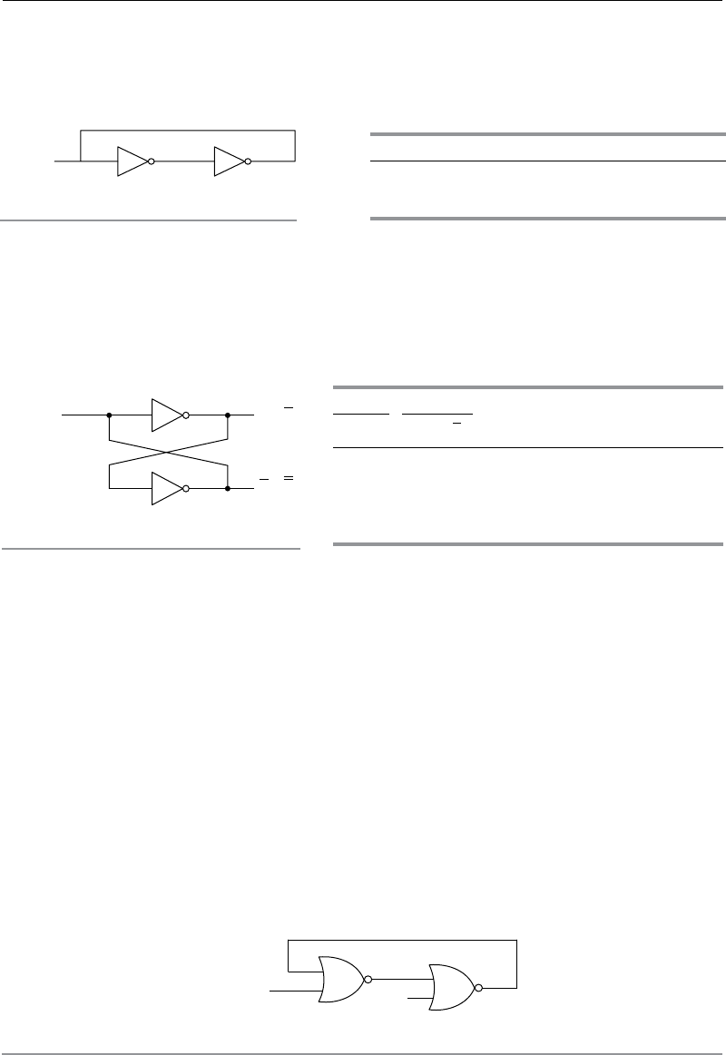
Two inverters, connected in series with feedback (Figure 7.6), are used to produce two
stable states i.e. either logic-0 or logic-1 state. The line connecting the output of inverter-II
back to the input of inverter-I is called feedback line.
O
1
(I)
O
2
O
3
I II
FIGURE 7.6 | Basic latch
TABLE 7.1 | Truth table
I O
1
O
2
O
3
0 0 1 0
1 1 0 1
Let Input, I is 0 then output of inverter-I, O
2
becomes logic-0 (Table 7.1). Output, O
2
acts
as input for inverter-II and produces logic-1 state. Since, output, O
3
of inverter-II acts input,
O
1
, of inverter-I. So, output, O
2
of inverter-I and output, O
3
of inverter-II remains same. Two
stable ...


