May 1998
Intermediate to advanced
720 pages
18h 25m
English
A disturbance signal is commonly found in control systems. For example, wind gusts hitting the antenna dish of a tracking radar create large unwanted torques which affect the position of the antenna. Another example, are sea waves hitting a hydrofoil’s foil which create very large unwanted torques which affect the foil’s position. (See Figure 1.30b). Maximum lift for the hydrofoil is achieved when the bow foil is at an optimum angle of approximately 40°. Disturbing this angle by torques created from sea waves crashing into this foil can seriously affect the lift capability of the hydrofoil.
Disturbance signals represent unwanted inputs which affect the control-system’s output, and result in an increase of the system error. It is the job of the control-system engineer to properly design the control system to partially eliminate the affects of disturbances on the output and system error.
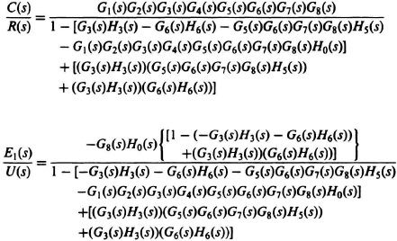
Consider the feedback control system shown in Figure 2.19a, which contains four feedback paths and a disturbance input U(s). Its corresponding signal-flow graph is shown in Figure 2.19b. We wish to find the transfer functions C(s)/R(s) and the transfer function of the error due to the disturbance. E1(s)/U(s). By inspection, these transfer functions are given by
The foregoing examples illustrate the simplifications made possible by use of Mason’s ...
Read now
Unlock full access


 O’Reilly covers everything we've got, with content to help us build a world-class technology community, upgrade the capabilities and competencies of our teams, and improve overall team performance as well as their engagement.I wanted to learn C and C++, but it didn't click for me until I picked up an O'Reilly book. When I went on the O’Reilly platform, I was astonished to find all the books there, plus live events and sandboxes so you could play around with the technology.I’ve been on the O’Reilly platform for more than eight years. I use a couple of learning platforms, but I'm on O'Reilly more than anybody else. When you're there, you start learning. I'm never disappointed.I'm always learning. So when I got on to O'Reilly, I was like a kid in a candy store. There are playlists. There are answers. There's on-demand training. It's worth its weight in gold, in terms of what it allows me to do.