4.22 PULSE RESPONSE OF SERIES R–L CIRCUIT
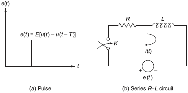
A pulse e(t) shown in Fig. 4.26(a) is given by e(t) = u (t) – u(t – T). This pulse is applied to a series RL circuit shown in Fig. 4.26(b) by closing a switch K. Applying KVL in the loop of Fig. 4.26(b), it can be written as that,

Fig. 4.26 (a) Series R–L circuit with pulse input, (b) series R–L circuit
Taking Laplace transform of Eq. (4.99), it can be written as follows,
Using Eq. (10.37) and putting i(0−) i.e., the circuit is initially ...
Get Signals and Systems now with the O’Reilly learning platform.
O’Reilly members experience books, live events, courses curated by job role, and more from O’Reilly and nearly 200 top publishers.

