Moving the Sketch to UTM Zone 2
You have seen how you can change the coordinates of the elements of the sketch. Now you change the coordinates so that they conform to locations in UTM Zone 2. These coordinates represent locations much further away so you can’t just click-click. Also, you want to place the control points in precise locations.
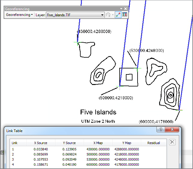
____ 12. Make sure Auto Adjust is set to off. Make the Add Control Points tool active. Click the most western point on the image that has UTM coordinates identified. Right-click and select Input X and Y from the resulting menu. Put in 430000 and 4288000 for X (Easting) and Y (Northing), respectively, and click OK. Notice a line extending from the designated point approximately north-northeast by north. Look at the Link Table to be sure everything is going according to plan. Click each of the other specified points and make links from them as well. The values of the coordinates, from left to right, are as follows:
(430000, 4288000) (extreme northwest)(500000, 4218000) (southwest of square island)(530000, 4248000) (northeast of square island)(600000, 4178000) (extreme southeast)The result should look something like Figure 5-11.
____ 13. Turn on Auto Adjust. Poof. The image disappears. Dismiss the Link table. Select Zoom To Layer on the TIF file. If you have done everything right, you will see the image, undistorted. By ...
Get Introducing Geographic Information Systems with ArcGIS: A Workbook Approach to Learning GIS, 3rd Edition now with the O’Reilly learning platform.
O’Reilly members experience books, live events, courses curated by job role, and more from O’Reilly and nearly 200 top publishers.

