BLOCK DIAGRAM
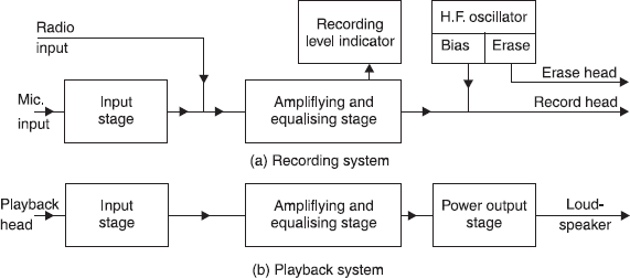
A tape amplifier can be represented essentially by the block schematic diagram of Fig. 11.10. Normally, the design of both (recording and playback) units will follow general a.f. practice, although attention must be paid to certain requirements of the equipment. Precautions will be required to minimise hum pick-up, and the overall signal-to-noise ratio should be at least 40 dB.

Fig. 11.10 Block schematic diagram of tape recording and playback systems
The attenuation of the bass response in a tape recorder takes place mainly in the playback head. The treble response suffers its greatest losses in the recording process. Thus, ...
Get Consumer Electronics now with the O’Reilly learning platform.
O’Reilly members experience books, live events, courses curated by job role, and more from O’Reilly and nearly 200 top publishers.

